


Fortunately, there is a proven and almost foolproof way to predict the reliability of a connector: Hertz contact stress. Electronic system designers can consult this indicator, which takes into account the main factors that generate current flow and resistance, to ensure that the connectors they choose will not fail them or their end users.
Connector reliability cannot be left to chance, and there is no reason to do so. Fifteen years ago, an IBM analysis demonstrated that a single indicator—high Hertz contact stress—virtually guarantees good connector performance.
It is surprising that this is news to many electronic system designers and manufacturers of products whose operation depends on connectors. Connectors are considered interchangeable components; that is, they are all equally good. This misconception leads to costly and troublesome failures and corrective actions that can be avoided simply by using connectors designed to withstand high Hertz contact stress.
Connector failures go undetected until use.
While the connector industry continues to see numerous innovations and significant advancements, customers still experience too many problems caused by component failures. In many cases, these problems only surface when finished products are used in the field. In any application, from medical devices to military radios, if end users discover issues and errors, these can have serious consequences for the manufacturers and suppliers of the faulty electronic systems that incorporate these connectors.
Companies that purchase connectors for their equipment don't want to use their customers as product testers, but they feel they have no other option because they are unaware of any proactive and predictive testing methods that can guarantee a connector will function reliably under all conditions. In short, they are unaware that using Hertz contact effort as a specification parameter for connectors can prevent most failures and the waste of a significant amount of money on corrective actions.
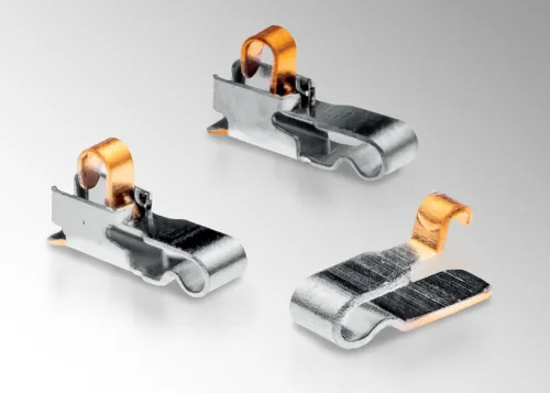
ITT universal contact. The mating zone of the ITT universal contact. Source: ITT Cannon
Hertz Contact Stress as a Predictive Performance Indicator
There is a foolproof method for predicting the reliability of a connector: Hertz contact stress. This parameter, also called Hertz force, is the calculation of the amount of stress created when two curved surfaces come into contact and deform slightly under imposed loads. In this case, a higher stress level is positive because it means there is more contact material, which is the basis for strong and reliable contact, as well as for the connector's performance. This was definitively demonstrated several decades ago by IBM engineers who analyzed different contact designs to find out if there was a common denominator that would allow them to predict the failure or success of a connector.
The analysis revealed that "the contact designs of failed connectors were always characterized by a low Hertz contact stress, while successful ones were based on designs with a Hertz contact stress that was an order of magnitude higher." This finding has been confirmed over the years and has become an increasingly important indicator as connector design has evolved to incorporate smaller, lighter connectors, lower-profile contacts, and models that can withstand harsh environments such as vibration and shock. The Hertz contact stress indicator is the best way for electronic system designers to ensure they include high-performing connectors in their products.
The physical principles:
To understand why a high Hertz contact stress almost guarantees good performance, it is important to understand the physical principles on which the operation of connectors is based. All metallic electrical connections are achieved by joining deformable metallic structures that create microscopic metal contact points or asperities (called "A-points") through which the current will flow. The number and location of these A-points are determined by the surface finish, the contact geometry, the strength of the metallurgy, and the force applied when joining the two pieces.
Once these metallic bridges are formed, the objective is to reduce and/or stabilize the factors that will decrease the current flow between points A. The total contact resistance is the sum of three types of resistance:
Rt = Rb + Rc + Rf
where
Rt = total contact resistance
Rb = gross resistance (caused by the metallurgy of the contact elements)
Rc = shrinkage resistance (caused by the size, number and distribution of points A)
Rf = skin resistance (caused by the formation of oxides, water vapor and other film barriers)

Figure 1: Contact resistance diagram. Source: ITT Cannon
The film is the most relevant resistive variable. All metals have films, which can range from "thin" or "normal" in metals like copper, aluminum, iron, and nickel, to "thick" in aged metals. The thicker the film, the higher the current resistance and the lower and more unstable the Hertz contact stress levels. The solution is not simply to increase the force joining the two metal pieces, which can lead to material fatigue and connector failure, but rather to improve the contact design. To achieve optimal and stable Hertz contact stress levels and good connector performance, the ideal connector is designed not with flat surfaces but with convex surfaces. The diagram below shows the typical difference between two contact designs. When the "normal force"—that is, the force pressing the two metal pieces together in opposite directions—is applied to these two connectors, the Hertz contact stress is higher in the connector on the right. This diagram shows that the accepted practice of relying on normal force to estimate contact performance is flawed. The convex connector on the right will offer greater reliability because the normal forces are channeled through a smaller surface area. This means there is more force per unit area available to penetrate the obstacle presented by a stable contact resistance: the contact films.
However, if the film is too thick, as is the case with aged metals, no force applied to two static metal parts will allow contact points A to form and current to flow. In these cases, the solution is a "slip" of the contact that introduces movement into the equation.
This "slip" is defined as the action of a moving contact relative to a static one to remove films and debris until a stable contact resistance is achieved. This is not easy. If the movement or force is insufficient, it will be impossible to penetrate the film. On the other hand, if the movement of the contact that pulls the film is excessive, it creates new debris that increases the contact resistance.
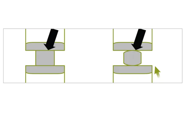
Figure 2: The commonly accepted practice of using normal force as an indicator of contact performance is incorrect. Source: ITT Cannon
The IBM study notes: “The geometries that create the maximum contact effort are also those that provide the smallest solution surface area. If the force per unit area is large enough to cut through the film and remove the debris, the contact will not ride up onto the film, and contact resistance will be maintained. The key, again, is Hertz contact effort, for the formation of asperities at the end of the travel and the contact's ability to maintain contact while moving.”
The IBM study demonstrating the enormous relevance of Hertz contact effort was conducted in conjunction with ITT engineers specializing in connectors. Based on the findings, ITT engineers redesigned many connector lines to achieve high levels of Hertz contact effort, and ITT's current product range includes ITT Cannon brand connectors that have proven capable of providing high Hertz contact effort in a wide range of applications. Most of these ITT Cannon connectors are available through Powell Electronics in Europe. These connectors are based on the ITT Cannon Universal Contact, which features a contact surface that meets ideal design specifications for achieving high Hertz contact force. The convex design offers numerous other advantages, such as 0.3N of force with only 0.1 mm of deflection and XYZ movement, ensuring a robust connection between the contact and the component.
Customers in many different markets, including portable medical devices, smartphones, smoke detectors, security alarm systems, military radios, memory cards, and GPS devices, among many others, rely on the ITT Cannon Universal Contact to meet their functional needs, confident that its high Hertz contact force ensures reliable performance.
ITT offers other connectors designed to provide high Hertz contact force, such as the ITT Cannon QLC (quad lock connect) line, which serves diverse needs in medical, industrial, and instrumentation applications, including portable ultrasound machines, patient monitoring systems, endoscopes and test equipment, and even semiconductor manufacturing equipment.
Similar to the DL Series connectors, the QLC connector is highly reliable and features a large pin count: up to 260 contacts for mounting on a printed circuit board. Thanks to technological advancements applied to small portable imaging equipment, ITT reduced the standard DL spacing to 0.8 mm, thereby reducing the overall size by more than 60 percent while maintaining the same number of pins.
The high pin count allows engineers to use various grounding methods to maintain signal integrity. The QLC connector interface utilizes EMI springs and a shielding locking mechanism to ensure uniform contact pressure around the connector's perimeter, creating effective EMI/RFI shielding. The high Hertz contact force is achieved through a superior cam system that adapts the contact system to its mated position. By leveraging Hertz contact force as a fundamental design parameter, ITT's product developers and engineers ensure that connector reliability matches its functionality. ITT connectors are designed to perform optimally for customers, guaranteeing they won't fail.
Hertz contact force is the best predictor of future connector performance. Companies that use, develop, or sell connector-based devices should evaluate these components for their ability to provide an optimal and consistent Hertz contact effort.
https://powell-europe.com/about-us
Author: David Camison Tornavacas is the representative of Powell Electronics in Spain - https://powell-europe.com/