

Validating automotive and electrified vehicles, including xEVs, requires measurements after assembly. At this stage, space around components is limited, and cutting the wires is not feasible. While closed-core sensors can offer greater accuracy, they require conductors to pass through their central opening. This presents significant logistical challenges during installation and removal in late-stage production testing.
Split-core current sensors, on the other hand, address these requirements by attaching directly around the wires. Since engineers often have to install and remove sensors repeatedly as testing progresses and they switch between waveform and power analysis, split-core sensors offer a much more practical installation method.
Lighter and more compact vehicle architectures have made these conditions even more demanding, limiting access for sensors rated for 1000 A, such as the previous CT1000S model, especially in applications with lower current ratings. Furthermore, conventional split-core current sensors do not achieve the required accuracy levels due to the challenges introduced by their clamp design.
Yokogawa Test & Measurement has developed the CT500SA and CT200SA to address these challenges. With accuracy levels comparable to closed-core sensors, a wide frequency bandwidth, and the ease of installation of a split-core design, both sensors offer compact measurement solutions ideal for confined spaces and a wide range of applications, from product development to real-world testing.
Key Features
1. Compact Measurement in Confined Spaces
The main sensor unit in both devices has compact dimensions of 110 mm wide × 62 mm high × 25 mm deep, making it ideal for space-constrained test environments. Each sensor incorporates a single release button for easy, one-handed clamp installation. The body also includes an M4 threaded hole and a flange slot, allowing the sensor to be fixed in position and directly improving measurement repeatability, as the outputs are position-sensitive.
2. High Accuracy, Wide Bandwidth, and Split-Core Design
The CT500SA and CT200SA guarantee accuracy of ±0.1% over a temperature range of -40 °C to 85 °C. In the 23 ±5 °C range, accuracy is further enhanced, achieving a maximum accuracy of ±0.09% of reading + 0.01% of full scale.
Both models guarantee accuracy an order of magnitude higher than conventional current sensors, equivalent to that of closed-core sensors, but with the convenience of clamp-on installation.
The available frequency bandwidths differ between the two models. The CT500SA offers a bandwidth of 500 kHz (-3 dB), while the CT200SA reaches 1 MHz (-3 dB). The CT200SA and CT500SA sensors can also measure switching frequencies, used in motor inverter validation, which require wide-bandwidth measurements. Both models maintain a phase accuracy of ±0.1° in the range 0.1 Hz ≤ f ≤ 1 kHz.
3. Versatile Measurements.
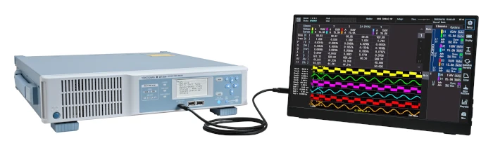
Typically, current sensors are compatible with only one type of instrument, either a power analyzer or a waveform analyzer. The CT500SA and CT200SA can be connected directly to both types of instruments without the need for a conversion connector or additional accessories.
In addition to saving time and labor by eliminating the need to change sensors, as well as reducing equipment costs, measuring identical signals improves reliability and eliminates the need to synchronize data.
Main target markets
• EV/xEV
• Automotive
• Renewable energy: photovoltaics / solar
• HVAC
Applications
• Measurement in near-finished xEV vehicles, where space is limited.
• Inverter efficiency analysis, involving wide-bandwidth measurement of pulse-width modulation (PWM) controlled outputs with harmonic content.
• Output current measurement and performance evaluation of photovoltaic systems.
• Current monitoring in HVAC and air conditioning systems.