Switches and server boards are adopting custom processors to meet the demands of services requiring high computing power and AI acceleration. Today's largest adaptive FPGA compute engines are housed in BGA packages up to 55 mm x 55 mm, and multichip ASIC processors can be significantly larger, especially with fan-out interconnects.
Automotive electronics are also growing, as embedded systems require higher power supplies for more powerful processors and expanded I/O to manage camera, radar, lidar, ToF, and inertial sensor channels. Control systems need larger connectors to manage additional data and power channels, and large bottom-terminated packages like BGAs, previously avoided due to inspection challenges, are now being adopted out of necessity.
The manufacturing challenge:
Equipment manufacturers serving these markets must be able to place large, heavy components accurately, at high speed, and with high throughput. This requires reliable and safe picking of trays or pallets, rapid positioning, and precise alignment before component placement. Through-hole parts, such as some types of connectors and transformers, need a reliable push-fit solution. Components can be large, tall, and bulky, while push-fit component assembly requires precise pin alignment before insertion. Historically, challenges like these, involving such large components, have exceeded the typical capabilities of standard surface mount placement equipment.
An inline solution is preferable to help assemblers maintain efficiency and productivity. Even better, using standard surface mount machines to place large BGAs and push-fit connectors saves the investment in specialized equipment or performing operations like offline connector assembly.
Flexible Placement
: Designing a solution for placing large, heavy components at high speed requires some critical changes to standard SMD assembly. Adaptations to the placement head are among the most important.
Gripper nozzles that combine suction with grippers are extremely effective for securely holding unusual components. Until now, acquiring such nozzles required assemblers to contact their equipment suppliers to design a custom gripper. As
larger and heavier IC packages and connectors, as well as inductors, transformers, and power components, become increasingly common, gripper nozzles can no longer be considered a specialized item. A more efficient approach is needed. Standardizing gripper and holder designs alleviates the time and cost pressures associated with a custom engineering project. Yamaha Robotics has standardized a range of grippers and holders (Figure 1) that allow for 60 different configurations to handle various component types and sizes. Choosing the right combination allows manufacturers to quickly and easily expand their component placement capabilities. 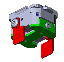
Figure 1. Configurable gripping nozzle with standardized grippers and support plates.
On the other hand, rubber-padded nozzles can provide an affordable and effective way to pick up large integrated circuits by applying suction directly to the top surface of the package. Yamaha is developing rubber nozzles in a variety of sizes up to 25 mm in diameter to lift heavier components. Part-specific nozzles designed to pick up components such as DIMM memory module expansion sockets for server cards are also under development. 
Figure 2. Nozzle for DIMM connectors.
R and Z Axes.
Before placement, the component must be correctly oriented by rotating the nozzle. When placing small, lightweight components, the R-axis motor can drive the nozzle directly at high rotational speed. Conversely, the greater inertia associated with large, heavy components requires more careful control of the movement to prevent the component from dislodging from the nozzle. While an obvious solution is to use a motor-driven reduction gear, backlash in conventional gear systems can affect accuracy. Yamaha's scissor gear is specially designed to eliminate backlash and allows for the alignment of components such as BGA integrated circuits with an accuracy of 0.005 degrees.
To handle taller components, simply increasing the Z-axis travel by a few millimeters significantly expands the range of parts that can be processed. An extended travel of 40 mm is sufficient for the machine to handle today's tallest automotive connectors.
Placement Force:
On the other hand, some connectors require a press fit, particularly board-mounted connections for automotive applications that are exposed to strong vibrations and shocks. In standard SMD assembly, these are designed with a placement force control of up to approximately 30 N. Precise control of up to 100 N is needed to ensure the correct insertion of connectors with a high pin count, which requires design changes and enhanced sensing and measurement capabilities.
The control system must also protect the component during insertion. Alignment detection (Figure 3) can detect if one or more pins are misaligned when the connector is presented to the board and avoid applying placement force, which could damage the component.

Figure 3. Alignment detection verifies correct alignment before applying press-fit force.
Machine vision and lighting systems used to check alignment must also be improved. Standard LED-based lighting systems typically used for component checking and alignment tend to illuminate the component body and the entire length of each pin or terminal equally. Under these conditions, the vision system may have difficulty accurately distinguishing the pin tip and assessing whether it is ready for insertion. A laser system can provide controlled, directional illumination to selectively light only the pin tips, thus allowing the vision system to verify that all pins are correctly aligned with their respective holes before insertion can proceed.
In addition, to withstand the increased placement force and maintain positional accuracy, the underlying board support structure and the pin push-in mechanism must also be reinforced.
placement
head to handle larger integrated circuits, taller components, and more challenging press-fit parts, as well as to place SMD chips and other small components at high speed. Special hardware and software features implement the extended R-axis control, Z-axis control, placement force control, and alignment detection described in this article. New nozzles and a specially designed clamping section accommodate larger components, and users can continue to use their existing nozzles to place parts in standard SMD, SOP, and QFP packages. A new nozzle health check function allows users to automate routine inspection and cleaning, ensuring regular and proper maintenance to maximize end-of-line performance and avoid unplanned downtime.
The LM head fits onto YRM machines using the same interface as other heads. On the other hand, the new feature recognition software for the YRM multi-chamber increases the maximum recognizable IC package size from 55 mm to 130 mm, and the maximum number of BGA balls from 4,000 to 20,000. This is a significant improvement that allows the system to recognize and align large FPGA and ASIC packages. 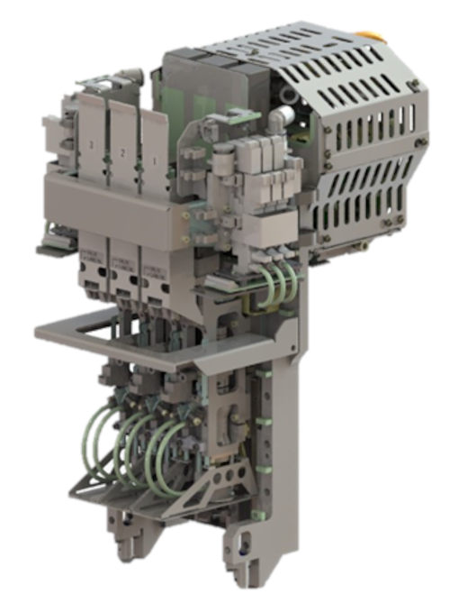
Figure 4. Placement head for large components up to 130 mm x 200 mm.
Conclusion
: To meet the latest demands from major customers in the telecommunications, data center, and automotive markets, equipment manufacturers must expand their capabilities to handle large and heavy components. The increased flexibility of current SMD mounters allows factories to quickly adapt and place all parts, from small passive SMD components to multi-chip ASICs and high-pin-count push-fit connectors, with high speed and efficiency. The placement head is the central point of change, requiring adaptations to the nozzles and grippers, force control, vision, lighting, and motion control on the Z and R axes. An ultra-flexible placement head incorporating these changes offers a cost-effective solution for manufacturers to capitalize on upcoming opportunities.