

Our aim is to address supervisory control and data acquisition (SCADA) in multi-vendor environments, recognizing the lack of support that exists when dealing with heterogeneous systems, since only an integrator or a technician specializing in the subject, with their extensive experience, could undertake such a project. In this sense, we wish to view industrial automation as an incremental process, with different time milestones, making the scalability and interoperability of systems a fundamental element when designing new plants or automated systems.
As a general working scenario, we wish to start with an industrial automation system that has grown gradually, resolving intercommunication problems as they arise. This results in communication silos, with zoned interoperability. This isolation is more pronounced the higher the designer is in the CIM communications pyramid (García et al., 2007). Consider, for example, a machine tool designed to operate autonomously with materials and equipment from one manufacturer, and whose functionality has been expanded with equipment from another. The solution for communicating data at this level is facilitated by information gateways, typically provided by third-party companies, enabling interaction with equipment from leading brands.
Today, it is necessary to implement remote monitoring (teleservice) of industrial automation systems for multiple applications: from mining, water treatment, oil and gas pipelines, pumping stations and traffic control systems to decentralized power generation and distribution in the wind, photovoltaic and district heating sectors, including "smart" advertising panels, weather stations, lighthouses, ticket vending machines or ATMs.
 The article is structured as follows. First, a brief overview of industrial communication networks is provided as the foundation of the monitoring system. Subsequently, a well-defined taxonomy of the capabilities offered by software packages dedicated to monitoring and acquiring process data is presented. The central part of the article describes the various elements and systems that can be used to perform data communication with a monitoring and control system. Different SCADA packages are reviewed, including their configurations and usage options in a multi-vendor environment, culminating in a discussion of the OPC protocol, specifically designed for system interoperability. Finally, conclusions are drawn from the various aspects analyzed.
Industrial communication networks
address the problem of information transfer between the different components of an automated system (Mackay et al., 2004). Figure 1 shows the industrial communication pyramid, based on the location/number of elements and their function (data or control). It should be noted that at the base, there are numerous industrial automation elements capable of sending small amounts of information. As you move up the pyramid, the number of elements decreases, but the amount of data that must be communicated increases.
The response time required by the communication subsystem at each level of the CIM pyramid can vary from a few microseconds for the process or field level to seconds for the plant level, thus determining the type of communication network needed to implement that communication.
Control networks are linked to the lower levels of the CIM pyramid because they must be able to support, in real time, information traffic consisting of a large number of small packets from a smaller number of stations than data networks. The separation between the two networks is not as clear as it might initially seem, since data networks tend to be given characteristics typical of control networks, as is the case with ProfiNet (Pigan et al., 2008).
The following software applications, among others, run on data networks:
Programs dedicated to the planning and logistics of all company resources (ERP - Enterprise Resource Planning).
Programs dedicated to the management of manufacturing execution systems, commonly known as MES (Manufacturing Execution Systems).
Computer-aided design, simulation, engineering, and manufacturing programs, known as CAD
/CAM/CAE (Computer-Aided Design/Manufacturing/Engineering).
General-purpose application tools that enable collaboration across all areas of the company.
Cellular Networks satisfy certain requirements that are specific or characteristic of the industrial environment, among which the following can be highlighted:
Operation in harsh environments (presence of strong electromagnetic interference, extreme temperatures, dust and dirt, etc.).
High security in data exchange within a precisely defined upper time limit, exhibiting deterministic behavior.
High reliability and availability of communication networks, achieved through the use of redundant electronic devices and/or physical media, and communication protocols with advanced mechanisms for detecting and correcting communication errors, etc.

Currently, industrial communications at the cell level are established using networks called Industrial Ethernet (II), whose data link layer is based on the standardized Ethernet medium access technique and the basic communication protocols (TCP/IP) used by office networks.
This greatly simplifies the implementation of electronic intercommunication systems between the data networks at higher levels and the control networks at lower levels of the CIM pyramid. The future trend is for a single standard to meet the needs of both types of networks. Industrial Ethernet networks primarily aim to redesign the hardware and software associated with the lower layers defined by the Ethernet standard, with the main objective of adapting them for use in an industrial plant environment.
Regarding the application layer protocol of the OSI model (Gordon et al., 2004) that should be used in combination with the protocols of the lower layers, there is currently no single solution. There is a wide variety of options such as Modbus/TCP, EtherCat, Profinet, etc.
SCADA Systems
SCADA is an acronym for Supervisory Control and Data Acquisition. A SCADA system allows a user to collect data from one or more remote devices and/or send control instructions to those devices from a control room. The Human-Machine Interface (HMI) system, responsible for facilitating human-machine communication, is of vital importance in a supervisory system.
SCADA Systems Classification
SCADA systems can be classified similarly to the classification discussed earlier for control and data networks, based on whether they only visualize the industrial process or can modify it:
Systems that affect the process: These are systems that allow the operator to intervene in and control the process, as well as monitor it.
Systems that do not affect the process: These are systems that only obtain data about a process and cannot modify its course.


Another possible taxonomy can be based on the location of the monitoring system, differentiating between local or remote monitoring, and between a screen-based HMI system and an industrial PC-based system with greater capabilities.
SCADA Systems Analyzed:
There are numerous monitoring and control systems, since each major automation equipment manufacturer provides its own proprietary SCADA system, and additionally, third-party companies provide SCADA software with different functionalities, focused on specific sectors, adhering to certain regulations, etc.
In this work, different representative SCADA systems have been tested since they are used by the main brands of industrial automation systems:
WinCC (Siemens)
CX-Supervisor (Omron)
Vijeo Citect (Schneider Electric)
Visu+ (Phoenix Contact)
KepWare Server - SCADA with multi-vendor OPC drivers
The following provides an overview of the characteristics of SCADA systems, referring the reader to the manufacturers' manuals for more in-depth technical information.
General Characteristics of SCADA Systems:
Although different in operation and with some specific functions, SCADA systems share common functionalities. They all use the Windows operating system due to licensing, code ownership, and compatibility with a wide range of existing systems. The following list outlines the general characteristics common to SCADA systems:
Trend charts, alarm management, etc.
Report generation.
Scripts for frequently used functions and routines.
Integration of ActiveX, COM/DCOM, OLE, and other controls.
Unified monitoring across screens/computers.
Integration between PLC programming software and the SCADA application.
Symbol and graphic library for screen creation.
ADO/ODBC support for reading and writing data to databases.
Communication with other applications via OPC.
Regarding a heterogeneous environment, the following issues should be specifically reviewed:
Inclusion of communication drivers for other PLC manufacturers.
Monitoring from a local computer (single-user) or multiple remote computers (multi-user).
Visualization and control via a web browser. Web publishing of monitoring and control screens.
OPC: The standard protocol for data exchange
The OPC (OLE for Process Control) standard is a communication standard used in process control and monitoring. This standard allows different data sources to send data to a single OPC server, which can then be connected to by various programs compatible with the standard. This eliminates the need for each program to have its own drivers to communicate with multiple data sources; a single OPC driver is sufficient.
OPC is a suite of protocols, among which the following stand out:
OPC-DA (Data Access) – The original, used for real-time data exchange between servers and clients.
OPC-AE (Alarms & Events) – Provides alarms and event notifications.
OPC B (Batch) – Useful for discontinuous processes.
OPC DX (Data eXchange) – Provides interoperability between multiple servers.
OPC HDA (Historical Data Access) – Historical access to OPC data.
OPC S (Security) – Specifies how to control client access to servers.
OPC XML-DA (XML Data Access) – Used for data exchange between servers and clients like OPC-DA, but instead of using COM/DCOM technology, it uses SOAP messages (over HTTP) with XML documents.
OPC CD (Complex Data) – Allows servers to expose and describe more complex data types in the form of binary structures and XML documents.


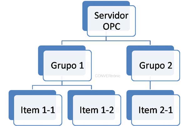
The design of OPC interfaces supports distributed network architectures. An OPC server consists of several objects that conform to the COM standard:
The server object: contains information about the OPC server configuration and serves as a container for group objects (Figure 2).
The group object: is used to organize the data that clients read and write (e.g., values on an MMI screen or in a production report). Connections can be established by exception between clients and the elements of a group. A group can be public, meaning it is shared by multiple OPC clients.
The item object: represents connections to data sources on the server (it is not the data source itself). It has the attributes Value, Quality, and Time Stamp.
Access to OPC items is done through OPC groups, and clients can define the rate at which the server informs them about changes in the data.
Multi-brand OPC: KepWare Server
. The KepWare Server software package will be used as a benchmark in the field of OPC servers. This package provides industrial OPC connectivity, allowing for the rapid configuration of communication between control systems through a diverse range of drivers or plug-ins and their components.
The package includes over 100 drivers that support hundreds of model types, easily transferring data to client systems. In most cases, OPC servers have been developed as simple programs that can only handle a single type of device or protocol at a time. As a result, multiple OPC servers are required to handle different types of devices or protocols. KEPServer has been implemented in two distinct components. The server component houses the entire user interface and OPC technology. Specific device drivers will be installed on this server component. KEPServerEX thus allows the concurrent use of multiple communication drivers.
To acquire data from a PLC or device, a channel and a device must be configured on the KepWare server, with a client application requesting this data. Almost all parameters can be modified while the server is running. New tags can also be added to the server without closing the client applications. When a new tag is added to the server, it becomes immediately available to any OPC client.
 All read and write operations can be viewed in the diagnostics window or monitored from the OPC client application using the provided diagnostic tags. This allows for better troubleshooting of communication errors. The diagnostics window also provides a real-time view of the protocol's activity.
Several communication examples between various PLCs and SCADA systems will be shown below. The PLCs used for communication testing were the OMRON CJ1M and the SIEMENS S7-300. The SCADA systems selected were OMRON's Cx-Supervisor, SIEMENS' WinCC, and SCHNEIDER's Vijeo Citect. An OPC server, specifically KEPServerEX from KEPWARE, was also included in this study. The way in which this study has been organized has been by SCADAs, so initially the configuration of the 2 PLCs to be connected using different communication channels is described, unified all of this in a single SCADA package.
Configuring Communications in a Siemens S7-300 PLC
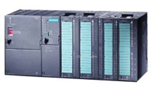
Regarding the connection between a potential SCADA system and the PLC, three options available through the PLC's hardware will be used (see Figure 3).
These options are serial (MPI protocol), Ethernet (TCP/IP protocol), and PROFIBUS. The SIMATIC STEP 7 software is used to configure and program the PLC. First, the project must be created (see Figure 4).
Each network (MPI/Profibus/Ethernet) must have a unique name within the automation project. The PLC must have a valid address within the defined range of the specific protocol. To do this, open the hardware configuration application and double-click on each element to be connected to each network. Figure 5 shows the basic configuration of each of the communication networks available on the S7-300 PLC.
The NetPro software provides an overview of the programmed connectivity (Figure 6).
Configuring Connections on the Omron CJ1M PLC
For the connection between the SCADA system and the CJ1M PLC (Figure 7), we will analyze the two possibilities offered by the PLC's hardware configuration. These possibilities are serial communication (Toolbus/Sysmac protocol) and Ethernet communication (FINS/TCP protocol).
Serial Communication: Toolbus and SysmacWay Protocols.
The Toolbus serial protocol is the most widely used by Omron tools due to its ease of configuration, and it is the default connection with the Omron PLC. Figure 8 shows the typical configuration screen in programs from the Omron CX-One suite.
The Toolbus/SysmacWay configuration is very similar; however, the installer must modify a hardware switch so that the PLC communicates serially using one protocol or the other. The SysmacWay protocol is a more open protocol, available outside of Omron's proprietary tools. For serial connection using the Sysmac Way protocol, the microswitch labeled 5 on the CJ1M PLC CPU must be in the OFF position.
Ethernet Communication:
An Ethernet communication card available in the CJ1M PLC rack is used. To correctly configure the ETN21 Ethernet communication hardware module, it is necessary to initially connect it directly to the PLC (via serial). Omron's native tools and drivers use the proprietary data communication protocol called FINS. If the connection is established via an Ethernet network, this connection will be a FINS over TCP communication.
The designer must configure the I/O table and the ETN21 unit, providing a FINS network address to which the node belongs and an IP address for Ethernet communication. Figure 9 shows how to access the configuration and assign an IP address to the ETN21 communication module from CX-Programmer.
Authors: Alfredo Gardel, Ignacio Bravo, José Luis Lázaro - Department of Electronics - University of Alcalá - Polytechnic Building. University Campus. Alcalá de Henares. 28871. (Madrid)