 To achieve maximum efficiency, wind turbine blades need to be optimized in shape and angle of attack. This requires ongoing aerodynamic research and development, conducted both in scale wind tunnels and through field testing on actual wind turbines. Scanivalve's electronic pressure scanners are ideal for aerodynamic improvement studies based on multi-point pressure measurements around the blade.
Pressure scanners have been used for years in wind tunnels to conduct studies on scale models of wind blades. The 64-channel ZOC33 pressure scanner can be used. However, in recent years, wind turbine manufacturers have begun conducting field research by placing the scanners inside the blade at different points along its entire length and while it is in motion.
Scanivalve, through its representative Instrumentps de Medida, SL, offers two options: the complete DSA3217 system, consisting of 16 pressure channels, an electronic multiplexer, and an all-in-one acquisition system; or the ZOC33 miniature scanner with 64 pressure channels and the E-RAD4000 remote acquisition system. Other scanners with fewer channels are available depending on the number of measurement points required. Pressures are recorded in real time at different angles of attack, wind speeds, and under any weather conditions. These tests are conducted 24/7 for months.
All Scanivalve pressure scanners incorporate a pneumatic calibration valve, which allows the user to purge the pressure inlet lines to eliminate condensation effects that would adversely affect measurements.
The user can purge the inlets as needed while the wind turbine is running. Conversely, when the turbine blades are not rotating due to lack of wind or are locked in safe mode, the user can perform a zero correction on all pressure sensors using a software command. This correction may take approximately 10 seconds.
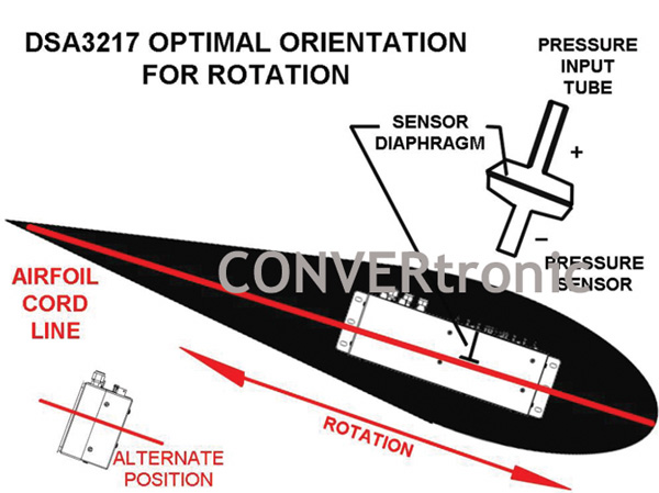
Flexible tubing is used to carry the measurement points to the pressure scanner located inside the blade. The scanner's location is critical for obtaining accurate results. They must be positioned as close as possible to the turbine hub to minimize centrifugal force acting on them during rotation. Near the hub, they must be positioned so that the pressure sensor diaphragms in the scanner are parallel to the direction of rotation, in line with the airfoil axis (see figure below), thus preventing the diaphragms from being affected by centrifugal force. Gravity must also be taken into account when correcting data. Gravitational forces are added to the measurements as the blade moves upward and subtracted from the measurement as it moves downward.
Available Pressure Scanners:
Pressure scanners can be configured to acquire data from 1 Hz to 625 Hz per channel.
The scanner model used depends on the available space and the type of tests to be performed. All systems incorporate Ethernet TCP/IP communication and provide readings in temperature-corrected engineering units.
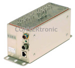
1. The DSA3217 model was developed by Scanivalve specifically for wind turbine applications. This special G model features a robust bayonet-type Ethernet connector. With 16 pressure channels per scanner and 10BaseT Ethernet communication, multiple DSA3217 units can be mounted on a single turbine blade, transmitting independent data in parallel. The maximum sampling rate is 500 Hz per channel.
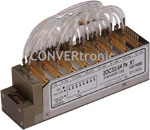
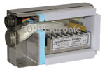 2. When space is limited and measurements are required at multiple points, the logical choice is to combine the ZOC33 scanners with the E-RAD4000 data acquisition system. Each ZOC33 contains 64 pressure sensors and can be housed in a ZOCTCU64 temperature-controlled unit. Up to eight ZOC33 scanners can be used with one E-RAD4000, allowing for a total of 512 channels. The compact E-RAD4000 system uses DSP technology and communicates via 100BaseT Ethernet. It can be installed on the turbine blade with the ZOC scanners and provides real-time data. The maximum reading rate is 625 Hz per channel.
Author:
Article provided by Instrumentos de Medida, SL.