


On the other hand, it might be time to upgrade the line to a dual-track configuration.
The optimal decision may depend on the typical cycle time of the board and the variety of components placed on each PCB. Furthermore, eliminating the placement bottleneck will highlight the limitations of other equipment on the line, such as the reflow oven. Therefore, the response to this immediate need for speed must be sensitive to the factory's future investment plans.
More SMT Mounts:
Adding an additional SMT mount to the line introduces extra placement capacity, although the improvement may be less than expected. A pair of SMT mounts on the line increases the effective distance each board must travel to reach the next process, thus increasing overall PCB transfer losses. Adding the extra SMT mount also increases the total line footprint by one unit, which can be problematic if space is limited.
Dual-Lane Line:
To achieve higher line throughput in a limited space, switching to a dual-lane line can offer advantages. With two lanes and two placement heads, a two-beam, two-lane SMT setup can mathematically double the line's placement capacity. In practice, however, the throughput increase may be smaller. Additionally, two transfer units are required: one to transfer plates from a single-lane screen printer to a dual-lane SMT setup, and another to transfer populated plates from the SMT setup to the reflow oven.
The dual-lane SMT assembly can be used in two modes. In parallel mode, two boards are loaded and filled simultaneously, as the two placement heads operate independently. The transfer time—for feeding the boards into the SMT assembly and applying the tooling ready for component placement—must be factored in when calculating the total cycle time. When working in parallel mode, only one side of the feeding bench can be used for each board lane. This can be a disadvantage when building boards with a wide variety of component types.
On the other hand, SMT assembly can operate in alternate mode. In this case, one lane's board is being printed while the second lane handles transferring and securing the next board. This reduces the board transfer time to zero. However, the two print heads cannot operate continuously, as each must wait to avoid interference with the other.
Comparing performance:
Given that the typical transfer time for a board is usually around two or three seconds, the alternative mode can achieve a faster cycle time when a small number of components need to be placed. It is in these situations that the savings in board transfer time have the most significant impact on reducing the overall cycle time.
As the number of components to be mounted increases, the time spent placing components represents a larger proportion of the cycle time. Consequently, the advantage of saving transfer time in alternate mode diminishes. In practice, if the cycle time exceeds approximately 15 seconds, the cumulative losses in alternate mode while either print head is idle to avoid interference outweigh the savings achieved by eliminating board transfer time. In such cases, parallel mode can offer greater productivity, provided there is adequate access to the feeder.
Another option:
Despite the potential speed improvement in either mode, a dual-lane SMTE assembly may not be the best solution for a single-lane line. In practice, SMT assembly production capacity is determined not by the number of lanes, but by the utilization of the placement heads. Higher productivity depends on keeping the placement heads active for as much of the cycle time as possible.
With this in mind, a two-stage, single-rail SMT assembly with two placement heads can have the same theoretical capacity as a two-way machine in parallel mode (Figure 1), while allowing access to the front and rear feeders.

Figure 1. The dual-stage SMT assembly offers dual-rail performance with the convenience of a single rail.
Plate transfer losses include the extra time required for lane splitting, which is performed within the SMT assembly. On the other hand, no drive unit is needed to remove the plates from the screen printing area. There is no waiting time to avoid printhead interference, and the compact size, equivalent to that of a single-lane SMT assembly, ensures a short total distance traveled for pick-up and positioning.
In general, if there are no special conditions related to the type of boards being mounted, a two-stage, two-head SMT assembly can increase productivity more effectively than introducing a dual-rail SMT assembly or two conventional single-head machines.
Understanding the Bottleneck:
When component assembly is the process restricting line throughput, the appropriate response is to increase assembly capacity. However, if the bottleneck is due to another process, increasing component placement throughput may be a wasteful investment.
To illustrate this point, consider an SMT line like the one in Figure 2, with the process cycle times shown. In this case, the first SMT assembly is the bottleneck and limits the line's cycle time to 40 seconds.
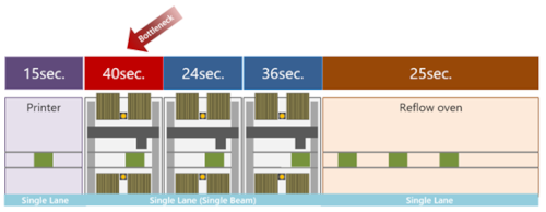
Figure 2. The assembly machine limits the SMT line's throughput.
Avoiding Idle SMT Assemblies:
In the example in Figure 3, the single-lane, two-stage upgrade has reduced assembly time, and the reflow soldering process now defines the line cycle time. This time cannot be reduced because the reflow profile has a fixed duration. In the illustration, each SMT assembly is significantly faster than the cycle time limited by the reflow and is idle for several seconds per cycle. The investment in assembly speed is wasted.
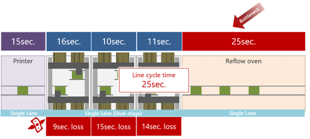
Figure 3. The reflux process limits the cycle time of the SMT line.
An effective cycle time of 25 seconds is fairly typical for reflow soldering. If the SMT assembly line is faster than this, the reflow process is most likely the bottleneck.
Improving the single-lane reflow process with a dual-lane oven reduces the cycle time to 12.5 seconds, as shown in Figure 4. This results in faster soldering of dual-lane components. The dual-lane SMT assembly can then interact effectively with the reflow oven. A transfer unit is required between the single-lane screen printing and the dual-lane SMT assembly.

Figure 4. Fastest cycle time with dual-lane reflow and component assembly. All SMT assembly heads are used.
The longest of the assembly processes defines the overall cycle time of the line. Although this SMT assembly is indeed limiting the line's throughput, the cycle time has improved significantly compared to the example in Figure 1, and all assembly heads are being fully utilized; therefore, in this example, no investment in assembly performance is being wasted.
A two-stage, single-lane SMT setup, as shown in Figure 3, can feed plates into a two-lane reflow using a cross-unit and also allows for a faster cycle time than a two-lane configuration. The two-stage machine also offers the flexibility to revert to single-stage operation for filling smaller plates, which have a shorter cycle time. A software tool such as Yamaha's Line Optimizer can automatically calculate and apply the most efficient settings.
The table summarizes typical options for SMT managers looking to improve the cycle time of their lines.

Table 1. Guidelines for cycle time improvement.
Conclusion:
Every SMT line contains a bottleneck. When it's time to upgrade, understanding its location is vital for directing investment appropriately. When the assembly cycle time is long, two-stage placement is a solid option. When the cycle time is short, investing in dual-lane reflow may be more effective.
Introducing dual-rail automation to a single-rail line is not a simple upgrade and involves compromises in feeder performance and availability. If space is limited and other single-rail equipment must be maintained, a dual-stage, single-rail SMT assembly can conveniently and cost-effectively increase productivity.
Article provided by Yamaha Robotics SMT Section