In this article written by MEAN WELL and translated by Electrónica OLFER, we discuss several solutions to meet these requirements.
- Upgrade to a higher-rated power supply: It's common to buy a 450W power supply to drive a 150W DC motor that has a peak current of 300%. However, this is an overkill design and results in a higher product cost and larger size.
- More power supplies in parallel to increase driving capacity: The second option is to connect multiple power supplies in parallel to drive the loads. However, more power supplies mean higher cost and less space for other components.
- Optimize the system to reduce peak current: Create a sequence to start the motors separately to decrease the starting current. However, this may negatively impact initial performance.
The above are obviously compromised solutions for driving motors. The best solution is to have a power supply suitable for handling continuous rated power and capable of generating high power peaks during transient periods. This not only effectively reduces system cost and size but also simplifies installation. To meet these needs, MEAN WELL and OLFER Electronics are launching the HRP-N3 series. This is a single-output power supply with power factor correction, featuring a short-duration peak power capacity of up to 350% (for 5 seconds). Three models are available in this series: HRP-150N3, HRP-300N3, and HRP-600N3.
To use high peak power products, several requirements must be met:
- Average output power (Pav) of an application ≤ rated output power (Prated) of the power supply
- Peak power width (duration): t ≤ 5s
Figure 1. Peak power period diagram
Example of power selection:
A 24VDC motor for a banknote counting application with the following power requirements: Maximum current: 66.7A (800W), peak power duration: t < 5 s. and duty cycle of 10%.
What is a suitable power supply for this application?
- Based on your peak power requirement, the HRP-300N3-24, HRP-600N-24, and HRP-600N3-24 are available options. We first selected the HRP-300N3-24, which has the lowest power rating, for this application.
- Perform a calculation following the formula and the maximum output power curve (Fig. 2).
Vin = 200V Maximum duty cycle = 10%
Pav=336W
Ppk= 800W
t = ≤ 5 seconds
≤ 336W
= 284.4W
If you choose a different duty cycle, you can use the interpolation method to calculate the corresponding maximum power according to the curve.
Conclusion:
- Based on the product's lower cost and smaller size, the HRP-300N3-24 model is suggested, with the input range adjusted to over 200Vac. If a full-range input is required, the alternative solution would be the HRP-600N-24 model.
- With peak power requirements of 800W yt < 5 sec, Period: ≧ 45sec, it means that the supply must cool down (or be in Pnpk mode) for at least 45sec before starting another peak power output.
- Non-peak output power (Pnpk): ≦ 284.4 W
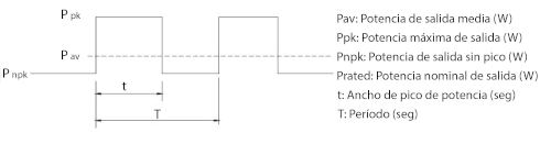 Figure 2. Maximum output power curve for the HRP-300N3 model
Application examples:
Case 1: Industrial robotic arms
A robotic arm is a programmable mechanical device that mimics the functions of a human arm and can be used to perform specific tasks. Robotic arms use motors to achieve joint movement. The HRP-N3 series can deliver up to 350% of peak power for 5 seconds to meet the transient power demands during motor startup. Consumers no longer need to spend more money on power supplies with the highest rating.
Case 2: Industrial Printers
An industrial printer uses motors to drive the rollers. The equipment consumes only a few hundred watts during normal printing; however, its transient power requirement reaches over 1000W when the rollers start operating. The HRP-600N3 model is perfectly suited for this application.
Models distributed by Electrónica OLFER.
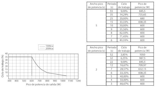 Figure 4. Application for an industrial printer