


Grid-tied inverters may or may not include a transformer for galvanic isolation; transformerless configurations carry a higher risk of ground faults. There are four main types of inverter designs. Two designs use a transformer (low-frequency or high-frequency), and two others are transformerless, incorporating either a DC chopper or a boost converter. For reasons of cost, as well as size, efficiency, and weight, transformers are becoming less common in newer designs.
Reference 1; IMS PV Inverter Database – Premium Edition – Latest Version - April 7, 2011.
Maximum Power Point (MPP) control, inverter control, and protection:
For each different topology, it is necessary to measure the instantaneous DC current and voltage at the photovoltaic panel output in order to determine the maximum power point (MPP), at which the maximum power output of the solar panel can be extracted. Current measurement is also required as input to the inverter's control loop, as well as to ensure protection in case of short circuits or overloads. Open-loop and closed-loop Hall effect technologies are used in the current and voltage transducers.
DC Current Injection Measurement:
In transformerless designs and high-frequency transformer configurations, the DC current allowed to be injected into the grid by the inverter must be limited to a maximum value between 10 mA and 1 A, depending on the different standards applied in different countries (reference standards include IEC 61727, IEEE 1547, UL 1741, and VDE 0126-1). This requires transducers with very high accuracy (greater than 1%) and low levels of thermal drift and gain. An ideal technology is the closed-loop fluxgate transducer (see Figure 1).
 Leakage Current Measurement:
In transformerless inverters that do not incorporate galvanic isolation, there is a potential for leakage currents to occur (see Figure 2). These are some of the associated risks:
1. The gap between the solar panel and the roof can provide a path for AC leakage current.
2. Any reverse electrical path from the AC line to the panel can connect the panel to the line voltage, with the consequent risk of electric shock.
3. Leakage currents can cause electromagnetic interference, current distortion in the grid, and system losses.
The ideal leakage current measurement from a safety perspective should be contactless and non-intrusive. 50/60 Hz AC leakage currents will be small, typically up to 300 mA, and can be measured as a residual component of a differential current measurement across multiple conductors. The measurement must detect a sudden 30 mA increase in leakage current, which could indicate that someone is touching a panel. Accuracy, and especially low thermal drift and gain, are key requirements to ensure the resolution of these small current measurements. The ability to accommodate multiple conductors within the transducer aperture for single-phase or three-phase systems is a significant advantage.
 Measurement of Ground Fault Current:
Safe monitoring must detect a current in the event of a ground fault caused by an insulation defect in transformerless designs. This current can be AC or DC, depending on where the fault occurs and whether the photovoltaic panel is grounded or not (see Figure 3). Similar requirements apply to leakage current measurement. Accuracy, while still important, is less critical in this case since short-circuit currents are larger than leakage currents. All these requirements for measuring residual current in transformerless inverter designs are fundamental for safety and must comply with all relevant standards.
 Closed-Loop Magnetic Induction Technology:
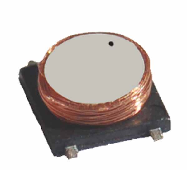
Closed-loop magnetic induction technology offers the necessary levels of accuracy, reliability, and isolation for measuring small currents. LEM has applied this technology to create its “CTSR” current transducers (Figure 4). Closed-loop current transducers measure currents across a wide frequency range, including DC.
For higher frequency ranges, these transducers operate similarly to (passive) current transformers; however, at DC and low frequencies, the voltage induced in the secondary winding (measured) is too low to control a sufficiently high current in the secondary and to utilize the same principle. In this domain, the magnetic flux density in the transducer core is measured by a sensing element, and a voltage is applied to the secondary circuit that, above all, keeps the flux density close to zero, thus creating a closed control loop.
CTSR Features:
The CTSR transducer uses a magnetic induction detector for feedback instead of the Hall effect sensor used in standard closed-loop transducers. This results in higher voltage per unit of current link, or "open-loop sensitivity." This technique also exhibits low offset drift. The CTSR magnetic head has been optimized to measure residual current (the algebraic sum of the currents flowing in the wires through the transducer aperture), with a maximum value of less than 1 A, when the primary currents are on the order of several tens of amperes in each wire.
The CTSR also incorporates a self-test function and a demagnetization function that eliminates any magnetization offset, making it suitable for both single-phase and multi-phase networks. Inside the device, an ASIC performs signal processing; the circuit elements form an oscillator which, together with the magnetic induction, drives it to saturation every half-cycle at a frequency of several hundred kHz. A DC magnetic flux present in the magnetic induction core causes a change in the duty cycle of the control voltage (Figure 5), and this change indicates the value of that residual flux.
 The signal processing stages comprise duty cycle demodulation, frequency response compensation, an integrator, and a bridge amplifier that supplies a secondary current. This output architecture can provide a higher (doubled) voltage to the secondary circuit: in this configuration, the load (or measured) resistance is floating, and a differential amplifier, which is part of the ASIC, is used.
The magnetic core comprises a pair of magnetic layers (Figure 6) containing the magnetic induction in a construction that protects the magnetic induction from any parasitic magnetic fields. Closed-loop magnetic induction technology has achieved accurate measurement of very small residual DC and AC currents with very low offset and gain drift over a wide operating temperature range of -40°C to +105°C. The devices can be mounted on a printed circuit board and are lightweight components (28g) with a 20.1 mm diameter opening for multiple leads. Residual current capacity measures the sum of all instantaneous currents flowing through the opening, in single-phase or three-phase configurations, and can withstand an overload pulse of 3300 A for 100 µs, with a ramp-up rate of 500 A/µs. The conductors can carry primary currents of up to 30 A/wire, AC or DC.
Standards Compliance:
The transducers meet the requirements of the latest reference standards, such as VDE 0126-1-1, UL 1741, DK 5940, and IEC 61010-1, for parameters such as creep and clearance distances (11 mm) and a comparative tracking index (CTI) of 600 V. The power supply requirement is +5 VDC; an additional pin provides access to the internal reference voltage (2.5 V), which can be used as the reference voltage for an A/D converter. This extra pin can also accept a reference supplied by an external signal processor or A/D converter to cancel reference temperature drift. The transducer design allows for a version with four current leads integrated into the primary for PCB mounting (three-phase currents in addition to test or neutral). Versions for higher currents measuring up to 3 ARMS are also available.

Conclusion:
Thanks to efficient conversion electronics that help ensure maximum profitability and feed energy back into national power grids, solar energy is a competitive energy source poised for further expansion worldwide. Advanced transducer technology offers a key element that will solidify the quality, safety, reliability, and efficiency of this new generation capacity.
Author:
Bernard Richard, Claude Gudel and Stéphane Rollier, LEM.
The authors:
Bernard Richard (