While supercapacitors require certain precautions, they are replacing batteries in data storage applications that need high-current, short-duration backup power. They are also used in various high-power peak applications and portable devices that require bursts of high current or momentary battery backup. Compared to batteries, supercapacitors provide higher power peak bursts in smaller form factors and have a longer operating life across a wider range of operating temperatures. Compared to standard ceramic, tantalum, or electrolytic capacitors, supercapacitors offer higher energy density and greater capacity for a similar size and weight. Furthermore, the operating life of a supercapacitor is maximized by reducing the capacitor's maximum voltage and avoiding high temperatures (>50°C).

'
Summary of supercapacitors versus batteries:
• Batteries:
• Good energy density
• Acceptable power density
• High ESR at low temperatures
• Supercapacitors:
• Acceptable energy density
• Good power density
• Low ESR, even at low temperatures (x2 at -20°C compared to 25°C)
• Limitations of supercapacitors:
• Limited to 2.5V or 2.75V max.
• Excessive inrush current upon battery insertion
• No reverse current protection in holding applications
• Advantages of supercapacitors in series:
• Better energy utilization
• E = 1/2 CV2
• Simplify last resort/backup circuits
• Buck vs. boost for 3.3V backup
• Good for high-power backup at industrial temperatures
• Potential problems for capacitors in series:
• Supercapacitors with different capacitances
• Supercapacitor leakage mismatches can cause overvoltage over time: cells require continuous balancing
• Supercapacitor capacitance and ESR degrade over time, but not always at the same rate
• Supercapacitor degradation is accelerated by overvoltage and high temperatures
Design Challenges with Supercapacitors
Supercapacitors offer advantages; however, when faced with charging energy storage devices in series, the designer of the final product may encounter problems such as cell balancing, cell damage from overvoltage during charging, excessive current consumption, and a large solution that takes up a lot of space when space is scarce.
Cell balancing in capacitors connected in series ensures that the voltage across each cell is approximately equal; a lack of cell balancing in a supercapacitor can lead to overvoltage damage. External circuitry with a balancing resistor for each cell is one solution to this problem. The value of the balancing resistor will depend on the supercapacitor's operating temperature and charge/discharge profile. To limit the impact of current draw from the balancing resistors on the supercapacitor's energy storage, designers may opt for a very low-current active balancing circuit. Cell mismatch can also originate from varying leakage currents. Leakage current in capacitor cells starts at a fairly high level and then decreases over time. However, if the leakage current differs for different cells in series, they may be subjected to overvoltage after recharging unless the designer addresses the leakage with balancing resistors. However, balancing resistors load the circuit with unwanted components and load current.
Challenges in the design of supercapacitor charger ICs
Among the most complicated aspects that a designer must consider when starting a supercapacitor charging project are these requirements:
• High efficiency and high charging current. A high-efficiency, high-current buck-boost supercapacitor charger/balancer includes all the features and functions necessary to take advantage of supercapacitors. Discrete solutions, when possible, are more complex, larger, less efficient, and less accurate.
• High accuracy and load sharing capability. Limiting the input current with an accuracy of +/- 2% and sharing the input load allow multiple loads to share the entire capacity of the same power supply with minimal degradation/margin. This functionality is not practical with a discrete solution.
• Active balancing. Supercapacitor systems typically use mostly dissipative (resistive) balancing. Active balancing efficiently transfers the charge between capacitors, eliminating the power losses and corresponding recharge cycles of dissipative methods.
New solutions for backup systems with supercapacitors.
A supercapacitor-based charging solution with a buck-boost IC that addresses the problems mentioned above must have the following characteristics:
• Flexibility, as it must operate efficiently in either boost or buck modes
• Ability to perform active load balancing with the capacitor's programmable maximum voltage
• Capable of supplying high charging current
• Precise and programmable limiting of the average input current
• Small size and low profile solution
• Advanced packaging to improve thermal performance and space efficiency
 LTC3128 Buck-Boost Supercapacitor Charger with Active Balancing.
The LTC3128 is a high-efficiency buck-boost supercapacitor charger with input current limiting and active load balancing for one or two supercapacitors in series. It features programmable input current limiting up to 3A with +/-2% accuracy, preventing power supply overload and minimizing capacitor recharge time. High-efficiency active load balancing eliminates external ballast dissipation resistors, ensuring balanced operation and charging even with unbalanced capacitors and less frequent recharge cycles. Programmable maximum capacitor voltage adjustment actively monitors and strengthens the voltage between each capacitor in series, ensuring reliable operation as capacitors age and develop capacitance mismatches. The low-noise buck-boost topology allows the output supercapacitor to be charged whether its value is higher or lower than the input. Low RDS(ON) synchronous switches and low gate charge provide high-efficiency conversion to minimize the charging time of the storage elements. This combination of features makes the LTC3128 ideal for safely charging and protecting large capacitors in backup power applications. Figure 2 shows a typical backup application circuit.
 The LTC3128's input current limit and maximum capacitor voltage are programmed using a single resistor. The average input current is precisely controlled within a programmable range of 0.5A to 3A, and the maximum voltage across each capacitor can be set between 1.6V and 3.0V. Other features of the LTC3128 include a quiescent current of <2μA when operating with VOUT in Burst Mode®, accurate indicators of power supply and power failure, and thermal overload protection.
Efficient Charging:
The LTC3128 uses PWM control of the average input current at a fixed frequency when charging the output capacitor(s). A proprietary switching algorithm allows the charger to seamlessly transition between buck and boost modes without any interruption in the inductor or loop current characteristics. The buck-boost charger topology is shown in Figure 3.
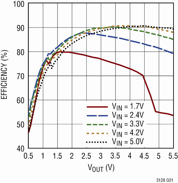 Two switches (D and E) connect SW2 to VOUT to provide high efficiency across the entire output voltage range. The LTC3128 achieves high efficiency, exceeding 90%, as shown in the graph in Figure 4.
Conclusion:
The LTC3128 is a DC-DC buck-boost supercapacitor charger controlled by the average input current. It utilizes a proprietary switching algorithm that allows the output to be regulated to a level above, below, or equal to the input voltage. The device is a compact, powerful, and flexible single-chip solution. Its ability to effectively and efficiently charge the supercapacitor in either the boost or buck direction, while also protecting and balancing the cells, greatly simplifies a task that has traditionally been very difficult. For more information, visit www.linear.com/products/supercapacitor_chargers