Thanks to their unique characteristics, tantalum capacitors are used in many different applications and, in some cases, can serve as a replacement for aluminum electrolytic capacitors or MLCCs. In the following article, we will describe their design principles, construction, advantages, and disadvantages, and outline the criteria to consider when selecting capacitors.
• Design, construction, and production of capacitors
• Surface-mount (SMD) capacitors – dimensions and specifications
• Through-mount (THT) capacitors – dimensions and specifications
• Advantages and disadvantages
Design and Construction of Tantalum Capacitors:
Capacitor production is a complex process in which the parameters of each stage must be selected and configured with perfect precision. In this article, we present a description of this process based on the Kyocera-AVX.
,
and a dielectric. The production process for this type of capacitor begins by compressing tantalum powder around a wire of the same material and then sintering it at a high temperature to create an anode. The high temperature causes the powder particles to bond (creating the structure described here), but to obtain a specific set of parameters, the appropriate sintering temperature and time must be precisely determined. A sintering time that is too long or a temperature that is too high reduces the capacitor's capacitance, while a sintering time that is too short or a temperature that is too low increases it. In practice, this means that the capacitor's parameters (capacitance and operating voltage) are already determined at the powder selection stage. It is also important to remember that many stages of the production process are influenced by factors such as the size (on the order of several micrometers) and shape of the powder particles.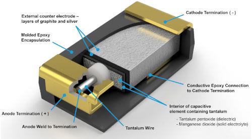
The capacitance of tantalum capacitors is determined by the following formula:
ε – dielectric permittivity
ε0 – permeability to free space
A – dielectric surface area
d – thickness of the dielectric layer
dielectric
is the "heart" of every capacitor because it "traps" energy in its electric field. Tantalum oxide (Ta₂O₅) is used as the dielectric in tantalum capacitors. As mentioned earlier, the sintering stage is followed by the formation of the dielectric layer. Tantalum is a conductor, so it cannot be used as a dielectric. Therefore, the components undergo an anodizing process, meaning they are immersed in an acidic solution heated to 85°C and subjected to an electric current. This causes a chemical reaction that creates tantalum pentoxide (Ta₂O₅) on the anode surface. The thickness of the dielectric layer depends on the voltage, so the current is initially kept constant until the selected voltage is reached. This voltage is then maintained at this level until a dielectric layer of uniform thickness is obtained across the entire surface of the component. Tantalum capacitors become polarized due to reactions that occur during the formation of the dielectric layer. An oxide layer forms between the tantalum oxide and the pure tantalum, acting as a semiconductor. This dielectric layer forms at a voltage higher than the capacitor's operating voltage; depending on the series, this voltage can be two to four times greater than the capacitor's rated operating voltage.
Cathode:
The next stage of the production process involves forming a cathode as a result of the pyrolysis of manganese(II) nitrate to manganese(IV) oxide. This is done by immersing the components in an aqueous solution of manganese(II) nitrate and heat-treating them to remove the water. This operation is repeated several times to ensure the cathode achieves the correct thickness. The elements are then coated with graphite and finally with silver. The graphite is used to separate the silver and manganese oxide, which could otherwise react and negatively affect the component's properties. In the cathode formation process, a polymer can also be used instead of manganese; this solution has many advantages, although it is not entirely without drawbacks.
Tantalum and Tantalum/Polymer SMD Capacitors.
Surface mount capacitors (SMDs) are the most common type of tantalum capacitors. SMD tantalum capacitors are sized to fit standard MLCC capacitor case sizes, allowing MLCC capacitors to be replaced with tantalum capacitors without resizing the PCB. Tantalum capacitors are specified not only for their length and width (as with MLCCs) but also for their height. Therefore, the appropriate letter from the Latin alphabet is added to each of these dimensions. Additionally, parameters such as voltage, capacitance, and polarity are specified on the capacitor case. A detailed description of these markings and dimensions follows.
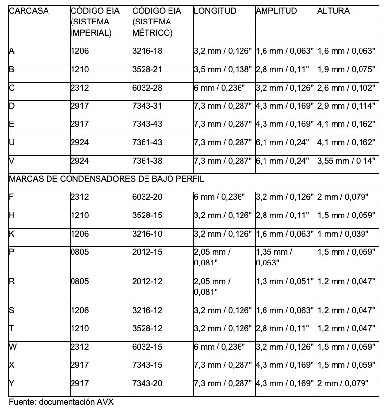
As we have already explained, the parameters of a capacitor are indicated on its casing. Below is a list of brands for various types of capacitor casings in the KYOCERA-AVX TAJ series.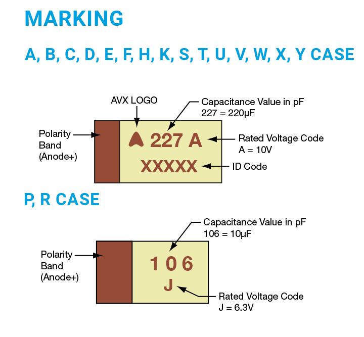
capacitors
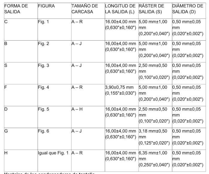
. Compared to SMD capacitors, the production process differs only in the final stage, during which the leads are connected. The parameters of THT tantalum capacitors are also marked on the casing.
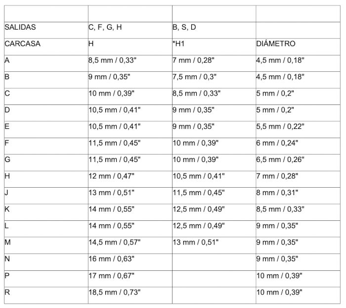
Below we describe the pinout shapes and the cases compatible with them.

Advantages of Tantalum Capacitors:
Tantalum capacitors offer numerous advantages, making them ideal for a variety of applications. They can also be used to replace or support aluminum electrolytic capacitors and MLCCs, saving PCB space. One of the most important characteristics of tantalum capacitors is their parameter stability over a wide temperature range, meaning they maintain stable capacitance values from -55°C to 125°C. Another advantage is the absence of DC bias, because unlike MLCCs, tantalum capacitors do not lose capacitance when DC voltage is applied to the signal line. An additional benefit is that the lifespan of tantalum capacitors is very similar to that of ceramic capacitors. In this respect, tantalum capacitors have another advantage over MLCC capacitors: they are not subject to aging (as is the case with Class 2 MLCC capacitors), meaning their capacitance value does not decrease over time. Tantalum capacitors do not age, thus maintaining their parameters for many years. Furthermore, their spongy structure ensures high volumetric efficiency. For example, the volumetric efficiency of standard SMD aluminum electrolytic capacitors is 11.8 µFV/mm³, while for tantalum capacitors, this parameter is 63 µFV/mm³ or higher. This means that tantalum capacitors can achieve a capacitance several times greater than that of aluminum electrolytic capacitors of a given size. Tantalum polymer capacitors have a low equivalent series resistance (ESR), which ensures higher efficiency and a lower AC ripple current rating during operation. That's why tantalum/polymer capacitors are an excellent solution in applications such as medical equipment, IoT, DC/DC converters, and smart measuring instruments. Thanks to the lower ESR resulting from the use of the polymer, the systems used in various types of projects can be much smaller, which is especially beneficial in space-constrained applications, such as wearable electronics, IoT, and signal processing devices.
Disadvantages of Tantalum Capacitors
Unfortunately, tantalum capacitors also have several disadvantages that make them suitable only for certain applications. One such disadvantage is power reduction, meaning that an operating voltage lower than the component's rated voltage must be selected. In the case of tantalum capacitors, this value can be reduced by up to 70%, meaning that a capacitor with a rated voltage of 35V should operate at 12V when high currents or sudden voltage spikes occur in low-impedance circuits. Therefore, the actual operating voltage is reduced to maintain an adequate level of reliability. It should be noted that a 50% voltage reduction is acceptable in most applications, and further reduction may result from higher operating temperatures (above 85°C). Remember that tantalum capacitors are susceptible to failure caused by overcurrent or overvoltage, as well as by improper installation. Tantalum capacitors cannot be mounted in any way due to their specific polarity, which must be respected to avoid operational problems. Therefore, pay close attention to the polarity markings and the installation conditions (flux). Another disadvantage of tantalum capacitors is their failure mode; avalanche breakdown causes a short circuit. Tantalum/polymer capacitors are more resistant to this due to their low ESR and lack of sensitivity to inrush current. Unfortunately, they are also sensitive to humidity, with each capacitor having an MSL level of 3 or higher (even up to MSL 5). Therefore, storage, mounting, and operating conditions must be carefully monitored. The final disadvantage of tantalum capacitors is their relatively low operating voltage. While MLCC and electrolytic capacitors have operating voltages of several hundred volts or even kV, the maximum operating voltage of tantalum capacitors is 125 volts.
Summary:
Factors such as a well-thought-out circuit design and careful selection of tantalum capacitors can largely mitigate their disadvantages. They have been used for decades in a wide variety of areas, from consumer mobile devices to highly reliable equipment for spacecraft. Despite their small size, tantalum capacitors provide high capacitance and power values, making them ideal for designs with limited size and weight. They are also a better choice when long-term capacitance stability is required across a wide range of temperatures and circuit conditions. As mentioned earlier, these products are available in many different form factors and with various cathode types, providing a broad range of parameters that make them suitable for a variety of applications.
Content produced by Transfer Multisort Elektronik Sp. z oo.