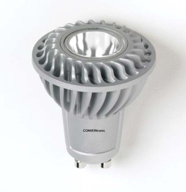
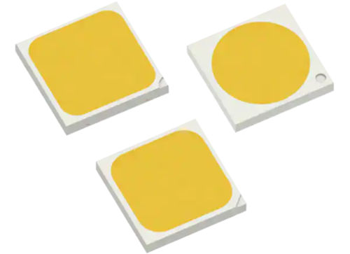
In terms of design, the most important elements are the driver and its converter. In an LED module, these components have the greatest impact on achieving performance targets. Similarly, the protection devices for these circuits significantly affect the module's reliability and lifespan, especially outdoors. Furthermore, to ensure safety and reliability, adequate fail-safe overvoltage and overcurrent protection is required.
Industry Standards
When choosing the driver converter topology and protection devices for these circuits and LEDs, designers of LED retrofit bulbs and luminaires must consider several options. A good starting point is to review the relevant industry standards and test specifications.
Table 1 shows the standards for countries with the highest demand for LED lighting. As the table indicates, two key aspects to consider are surge resistance and safety. The choice of isolated or non-isolated topologies, with the corresponding power levels, will determine the necessary level of safety for protection against short circuits, overloads, and transient overvoltages.
In the U.S., agencies are in the process of standardizing the performance, safety, and surge resistance applicable to LED lighting. The EPA's Energy Star specifications apply to LED replacement bulbs for residential and certain commercial uses. Both the Municipal Solid State Street Lighting Consortium (MSSSLC) template for LEDs on roadways from the U.S. Department of Energy (DOE) and the Energy Union's Performance Specifications for Outdoor LED Lighting for Parking Lots and Garages for Commercial Buildings are important documents, published in 2011 and 2012 respectively, that address the issue of surge withstand levels for outdoor LED luminaires.
Within this framework of standards and test specifications, designers are required to meet a series of performance objectives directly related to the controller topology and the required protection devices. These performance objectives include the following:
- LED operating efficacy (lumens emitted per watt consumed).
- Overall energy efficiency of the lighting module.
- Temperature regulation of the LEDs and their control circuitry.
- AC power factor correction (PFC) for the driver circuits.
- AC harmonic generation (distortion).
- Compliance with EMI restrictions.
- Whether or not dimming is required.
- Reliability and lifespan of the LED driver (to match that of the LEDs).
- Necessary circuit protection devices.
- Optimization of the space occupied by electronic components (module size).
- Cost competitiveness.
Power supply options for drivers: advantages and disadvantages to consider.
The most common LED modules consist of a strip of LEDs connected in series and powered by a constant current driver with switching mode. This combination is usually the best option for achieving the desired brightness, controlling the color, and adding a dimmer switch if needed. If the power supply comes from the AC mains, the constant current source is often called a "self-contained inverter." This is the case with most retrofit bulbs and LED outdoor luminaires.

When making a decision regarding the topology of the converters, safety and UL company recognition carry significant weight, and this, in turn, influences the choice of components, electrical insulation, module size, as well as the way in which circuit protection devices are used and, of course, also the costs.
Topology also affects energy efficiency and other performance factors. Although switching-mode converters are commonly used for LED drivers, specific topologies may be preferable for the converters depending on the application. The following are some general examples of topology options for AC-powered modules:
* Isolated and non-isolated linear controllers with constant current regulation.
* Buck or buck/boost converters (with or without FCP).
* Single-stage flyback controller with FCP.
* FCP + isolated half-bridge with constant V and I (eliminates the linear or DC-DC conversion stage).
In many of these topologies, synchronous rectification could also be considered, which can enhance efficiency at low output voltages. Due to space limitations, we cannot analyze all the possible approaches to LED driver design in detail here; however, we will present some examples to highlight certain aspects that might be sacrificed in exchange for others.
Advantages and disadvantages of isolated and non-isolated topologies
Many retrofit lamps and lower-power applications do not use isolated transformers. In these non-isolated solutions, inductors are used as harmonizing elements. Figure 1 shows two simplified examples of LED control circuits: the first, isolated, and the second, non-isolated with optional power factor correction (PFC).
To a certain extent, the term "unisolated" is not the most appropriate, since, for safety reasons, unisolated topologies also require the use of electrical isolation to protect (isolate) users from dangerous voltages. (Regardless of their topology, all modules must function safely in the event of a failure.) Among other factors, cost and module size must be considered when deciding which topology to use.
However, based on desired performance characteristics, industry standards, and test specifications, other factors may prevail in determining the topology. (See the list of performance objectives presented above.)
Isolated topologies:
The transformer can be a significant factor in terms of size, cost, and energy efficiency. It is partly responsible for power loss due to leakage inductance and reduced use of the winding area. To maintain a more constant current flow to the LEDs, larger components may be necessary for high power factor solutions.

While the power factor (PF) metric is related to total power consumption, the efficacy of the LED bulb or luminaire (lumens emitted per watt consumed) may be considered a primary factor due to industry standards such as Energy Star specifications. The PF is also important for LED lighting designed for Europe, which must conform to Class C as defined in IEC 61000-3-2. For applications with an input power > 25 W, where the limits extend to the 39th harmonic, the requirements are more stringent.
Furthermore, the transformer provides a degree of protection against transients and overvoltages on the primary side. This can reduce the number, size, and cost of circuit protection devices required on the secondary side.
From a component count perspective, the implementation of a given topology, such as that of a flyback controller, may be more important. For example, with a single-stage flyback (Fig. 1), compared to a two-stage flyback, the number of components, module size, and costs are reduced. Since only one power processing stage is required after the rectifier and filter, reliability is generally also increased.
One of the problematic areas in power supply design for controllers is the use of electrolytic capacitors, which are often among the first components to fail and whose lifespan is highly dependent on operating temperature. Effective thermal regulation is essential for a product's success. (We will return to operating temperature later.) In high-power-factor (FP) solutions, there is no large high-voltage storage capacitor, typically electrolytic, after the input diode bridge rectifier. In addition to reliability issues, large input capacitors distort the mains current and reduce the FP. Although a capacitor is used in the secondary circuit across the LEDs, a lower-voltage, longer-life device can also be used.
Unisolated topologies
Since non-isolated topologies do not use a transformer, their circuits are simpler and require fewer components. These topologies (generally a buck or buck/boost driver) are well-suited for LED retrofits in homes and other lower-power applications. With the appropriate control technology, these solutions can also achieve a power factor (PF) of between 0.95 and 0.98.

Even so, adding electrical insulation to protect users from dangerous voltages incurs another additional assembly cost, as LEDs require heat sinks to keep their temperature below a critical value. Since the heat sinks are exposed, this is not an easy task in the configuration of household light bulbs (A19).
When LEDs reach temperatures above 80°C, this results in a significant loss of efficiency and can also cause color changes. Therefore, the designer must control the temperature to maintain high brightness. Furthermore, excessive temperature poses a fire hazard and reduces the lifespan of both the LEDs and the driver.
The lack of insulation in the transformer also means that the conversion circuits and LEDs will be more susceptible to damage from AC power surges. Therefore, it is necessary to use more robust circuit protection devices for both the AC and DC sides of the lighting module.
Once again, and just as we did in the isolated return topology, capacitors must be considered. If the topology is not isolated, a relatively large capacitor will be necessary to maintain a constant current flow to the LEDs around the zero crossings of the AC power supply.
Whether you're considering an isolated or non-isolated topology, if LED lighting needs to be regulated, the design process will also be simplified by using a high power factor. As with previous products developed for incandescent bulbs, this allows for a reduction in the number of components in the dimming circuit, as well as the use of external triac controllers with phase-cutting.
Circuit Protection Requirements:
All LED drivers require various devices positioned in different locations (Fig. 2) to protect the circuits against overvoltage and overcurrent events. Currently, there are several key industry specifications and standards that you should review before beginning to design an LED retrofit bulb or outdoor luminaire. The recently established UL 8750 standard is the safety standard for the use of LED equipment in lighting products. It requires the use of a protective device to interrupt or limit the current flow that could result from an overload, in order to minimize the risk of electric shock and fire. For this purpose, the use of fuses is the most common and reliable technology for short-circuit and overload protection. These AC fuses are connected in series with the load and are available in a wide range of form factors, amperage and voltage ratings, breaking capacities, and mounting options to provide the engineer with design flexibility.

In the U.S., for retrofit lamps and indoor LED lighting, the EPA's Energy Star specifications require a resistance to oscillatory wave surges of up to 2.5 kV (Fig. 3).
* Test level: 2.5 kV/83 A, between phases (ANSI/IEEE C.62.41-1991, Class A operation)
* Number of surges: 7 common-mode and 7 differential-mode surges, 1 minute between each.
For countries outside the U.S., IEC 61547 calls for the surge withstand test of IEC 61000-4-5, which specifies the combined wave surge test (Fig. 4) based on the wattage of the LED lighting module, as detailed below. The core requirements for surge testing according to IEC 61000-4-5 include the following:
* For lamps and luminaires with their own ballast of < 25 W, 500 V/250 A: apply 500 V between phases with a 2-ohm source impedance and 1 kV phase-to-ground with a 12-ohm impedance.
* For luminaires > 25 W, 1000 V/500 A: apply 1 kV between phases with a 2-ohm source impedance and 2 kV phase-to-ground with a 12-ohm impedance.
* Number of surges: 10 shocks, 5 positive and 5 negative respectively at the 90°/270° phase shifts, with 1 minute between each shock.
In outdoor LED lighting, the susceptibility to high voltage surges, such as those caused by thunderstorms, is much greater. It is crucial that the sensitive electronic components of LED drivers, as well as the LEDs themselves, are protected against such high-voltage events. For outdoor LED lighting, such as streetlights, driveways, parking lots, and garages, the U.S. Department of Energy (DOE) has published a specification template that addresses performance and surge resistance testing. These luminaires fall under Category C High, indicating high exposure to natural phenomena.

Many cities and municipalities are already using the DOE specifications for tenders for LED lighting retrofit projects. The aim is to guarantee the long-term profitability of the investment in LED luminaires, given that these can cost two or three times as much as conventional lighting technologies.
Based on the physical location of the LED luminaire (see fig. 5), the IEEE C.62.41-2002 standard establishes the required level of surge resistance.
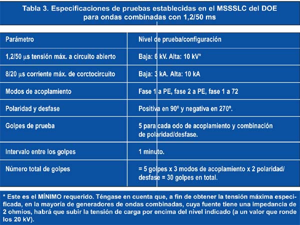
As specified in IEEE C.62.41-2002, overvoltage is characterized by a combined waveform with 1.2/50 µs for open-circuit voltage and 8/20 µs for short-circuit current. Table 2 summarizes the overvoltage levels that must be tested for different indoor and outdoor lighting applications.
The DOE MSSSLC references this standard in its specification template for LED roadway lighting for outdoor applications, specifically for Category C High. This surge level, at 20 kV/10 kA with a total of 30 shocks in different coupling modes and phase shifts, is one of the most stringent. Table 3 provides a brief overview of the test requirements for Category C High and Category C Low.
Choosing and Placing Circuit Protection Devices:
In the previous section, we analyzed the protection requirements for indoor and outdoor LED lighting applications. Here, we will describe the best way to comply with published standards and protect luminaires by choosing the appropriate components and their optimal placement within the circuits. Figure 2 shows a block diagram of a protection scheme that meets the safety and overvoltage standards.
In the figure, the three metal oxide varistors (MOVs) included in the surge protection device (SPD) block are used to ensure the product has a high level of surge resistance. The best option for responding to multiple 10 kA surges is the 25 mm metal oxide varistors with thermal protection. These varistors are designed to cover all possible current paths, including phase-to-neutral, phase-to-ground, and neutral-to-ground. Thus, for example, in the event of a lightning strike, these varistors will absorb most of the surge. However, some energy will still be allowed to pass through, provided the next smaller varistor in the LED driver can handle it.

In the AC power supply block, the selection of fuses and metal oxide varistors for the AC power supply must be coordinated. This means that the energy required to melt the fuse (its I²t value) must be high enough to allow the varistor to operate under overvoltage, but without causing the fuse to blow. The fuse should only blow in the event of an overload or short circuit.
In some cases, even with a varistor in the AC power supply, the controller may not be able to withstand a voltage surge. In such cases, a transient voltage suppressor (TVS) diode can be added at the converter stage input, as shown in Figure 2. This will allow for better retention of any energy that might otherwise pass through the varistor, thus protecting the controller circuit. To protect the LEDs, it may be necessary to use a positive temperature coefficient (PTC) device, a second transient voltage suppressor diode, and the open-circuit LED protection devices (PLEDs) shown in Figure 2. The PTC device limits the DC current under overcurrent or overtemperature conditions to protect the LEDs. The second transient voltage suppressor diode protects against any residual energy that may have passed through the LED circuit.
LED open-circuit protection devices are unique components that allow bypass for open LED strips and protect them against electrostatic discharge and reverse polarity. A constant current source driver has a maximum output voltage (open circuit) called the "available voltage"; this voltage is present when an LED fails (the most common type of failure). This will activate the LED protection device, conducting current around the open LED. (The power dissipation of these devices is less than that of a lit LED.) The remaining LEDs will stay lit, and in many applications, the failure of a single LED is not a serious problem, or may not even be noticeable.
The authors
– Jim Young graduated from the University of Arizona with a degree in electrical engineering and has 35 years of experience in power electronics. His expertise includes designing power supplies for airborne military platforms, high-reliability telecommunications and medical applications, and consumer electronics. He currently designs LED drivers and control ICs for ON Semiconductor.
– Usha Patel is a graduate of the University of Southern California and a registered professional engineer. She currently heads the marketing and sales department for Latin America at Littelfuse. In addition to her responsibilities in Latin America, she also leads the company's global initiatives related to the LED lighting market.