In general, the main driver behind the growth of LED lighting products is the increased efficiency (more lumens of light generated per watt of energy used) achieved by LED technology.
LEDs have different electrical requirements compared to the incandescent lamps that preceded them. Furthermore, the optimal power supply solution for controlling LEDs varies depending on the power level and the overall system requirements.
In traditional lighting solutions (such as incandescent bulbs), the load appears resistive. Energy consumption, and therefore light intensity, was a function of the voltage applied to the light and the resistance of the bulb (according to Ohm's law). The intensity increases or decreases depending on the input voltage. Consider, for example, the headlights of a vehicle when the engine starts; while the engine is starting, the voltage from the battery is low, and therefore the headlights dim. Once the engine is running, the battery voltage recovers, and the headlights reach their normal intensity.
LED lighting solutions behave fundamentally differently from incandescent light. The intensity of LEDs is controlled by modulating their currents, and the resistance of an LED load varies with the applied load. Instead of using a constant voltage and resistance to maintain a constant light intensity, an LED requires a constant current. The way to achieve this varies depending on the power level of an LED.
For a very low-power LED, a circuit like the one shown in Figure 1 is simple and almost always sufficient. The effective resistance of the LED is very small compared to R, so the current through the LED is determined by V/R. The drawbacks are as follows:
1) The intensity is a function of the voltage. A change in V will cause a change in the current, and therefore in the intensity of the LED. Returning to the previous example of a vehicle headlight, the light would remain dim while the engine is starting.
2) The solution does not take advantage of the benefits offered by the efficiency of LEDs. Since R is very large compared to the LED resistance, most of the power is lost in R.
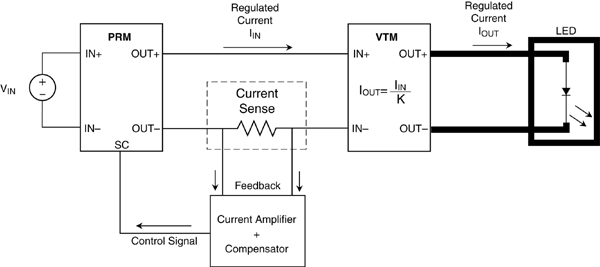
For higher-power LEDs, a current-controlled solution is needed to maximize the LED's efficiency advantage. Figure 2 provides an example of such a solution.
The V•I Chip PRM regulator and the VTM voltage transformer are designed to supply a regulated voltage. To use the PRM and VTM to power an LED, the PRM's operation must be modified to supply a regulated current. This is achieved by incorporating a Current Amplifier and Compensator.
Using the PRM and VTM to supply a constant current offers several advantages over conventional techniques. Introducing a VTM into a system provides current multiplication at the load point. The output current of a VTM is proportional to its input current according to a fixed ratio, K, as shown in the equation:
Therefore, in a current-controlled application, the input current to the VTM can be measured and regulated to control the output current. Measuring a lower current requires a smaller sensor that dissipates less power and improves overall efficiency. The V•I Chips themselves provide high efficiency and high power density, resulting in a small, low-temperature LED system that maximizes luminous flux in lumens per watt dissipated.
An important added advantage is that the current through the LED (IOUT in the previous equation) is not a function of the input voltage. Therefore, in our vehicle headlight example, the LED intensity would remain constant as long as the current through the LED remained constant, regardless of the battery voltage. This is possible because the PRM represents a variable negative resistance that can change with V, thus allowing a constant current to be maintained. Even more importantly, the PRM resistance is effective, not real, meaning that the power loss is minimal and not a function of the effective resistance value. Therefore, most of the power is lost in the LED, making this solution as
efficient and effective as the LED
itself.
Among the drawbacks of this solution is its complexity; obviously, it is a more complex solution than the one shown in Figure 1, and therefore its implementation requires more dedication and careful planning. With its greater complexity also come increased costs, so this solution is more appropriate for higher power LEDs, for which the power savings (and energy cost savings for the operation of the LED) compensate for the increased cost and complexity.
In summary, there are various power supply solutions for LEDs, ranging from simple to complex. Resistive current limiters (Figure 1) are simple and inexpensive, but inefficient and unsuitable for high-power LEDs. Adjustable current sources (Figure 2) maximize efficiency and size, but are more expensive and complex. However, adjustable current sources offer added advantages such as immunity to input voltage fluctuations, which may or may not be important for the overall system objectives. The designer of an LED power supply must be familiar with the different power supply solutions available for LEDs, as well as the overall system objectives.
Author: Paul Yeaman, Victor
More information or a quote