




 For nearly a decade, Microchip Technology Inc. has focused on intelligent power conversion applications to deliver more features and greater capacity for all types of power conversion applications. One of its primary areas of focus has been, and continues to be, the fully digital control of power converters/inverters using high-performance DSP-based microcontrollers with highly dedicated, high-speed, high-resolution peripherals, as well as dedicated controller families for hybrid control systems that combine microcontrollers and control loops based entirely on analog electronics. A closer look at these solutions reveals that neither the hybrid solutions based on analog electronics nor the fully digital solutions are 100% analog or 100% digital. Both urgently need their analog and digital counterparts to overcome certain limitations and thus offer a certain potential for their intended applications. The latest family of intelligent power conversion controllers, the MCP191xx series, marks a new technological leap by making converters smarter and focusing on dedicated power converter topologies and applications.
The first members of this MCP19111 product family merge a high-performance analog synchronous buck converter controller and an 8-bit microcontroller into a monolithic IC, thus offering advanced and flexible configuration, control, and monitoring capabilities, as well as the ability to integrate standardized or proprietary communication for multiple converters in a higher-power management structure. Unlike other existing hybrid POL controllers, the MCP19111 is fully programmable in C. This advantage provides complete flexibility to tailor the device to different application requirements, adapt to specific operating conditions, implement general monitoring tasks, and incorporate custom functions.
The wide input voltage range of 4.5V to 32V DC and output voltages from 0.5V, together with controllers that can reach up to 2A (source) / 4A (consumption), open up the possibility of supporting a wide variety of applications.
Digital Advancements:
The availability of a digital controller and a switched-mode analog regulator on the same semiconductor chip enables the integration of analog functions and digital control for direct manipulation of the compensation circuit, switching frequency, dead-time control, system-level thresholds, and many other functions during operation. Furthermore, since the microcontroller itself is integrated into the switched-mode analog regulator architecture, the need for additional auxiliary power supply functions or external MOSFET drivers has been eliminated.
 Figure 1 shows a high-level block diagram of the MCP19111 digitally enhanced analog power controller along with a typical application circuit. The switched analog regulator section fully covers all components of the analog control loop, including the MOSFET drivers, and also incorporates the auxiliary power supply for the microcontroller. The digital section comprises an 8-bit PIC12F midrange microcontroller core with 8kB of Flash and 256 bytes of RAM. It also offers up to 15 GPIOs, eight of which are additional analog inputs, an I²C/SMbus-based serial communication interface, external interrupts, and three free timers. Many internal signals, such as input voltage, output voltage, and inductor current, can be monitored directly on the chip itself without the need for external sensing.
The digital implementation even allows for reading the current duty cycle value, a very useful feature that, for various technical reasons, had previously been reserved exclusively for fully digital controllers.
Maximizing Efficiency:
In addition to its greater monitoring capabilities, the monolithic integration of a digital core also provides direct access to many parameters that are typically fixed by hardware or inaccessible in silicon. The most notable are adjustable dead time, programmable compensators, internal feedback calibration, programmable protection thresholds, and even the ability to switch between current and voltage control modes during full operation.
Adjustable Dead Bands
In synchronous buck converters, adjusting the dead band between the high-side and low-side switches has a significant impact on overall system efficiency. If analog controllers offer any dead band adjustment, the designer must consider some of the worst-case scenarios involving higher temperatures and loads, where the dead band should generally be at its maximum, and "program" this value in hardware, e.g., by adding capacitors and/or resistors. This inevitably results in higher core and diode losses, as the converter will most likely never be exposed to these worst-case scenarios.

A suitable solution would be to automatically adapt the dead time to certain load and temperature conditions. Unfortunately, incorporating a zero-crossing detector to always control the switches with an optimal dead time presents serious limitations for two reasons. First, all types of analog zero-crossing detectors are based on comparators. The fastest (and most affordable) analog comparators are characterized by typical propagation delay times of 15–20 ns, which, based on the results shown in Figure 3, are too slow to achieve the optimal level. Second, this zero-crossing detector would have to operate in the switched-mode of the half-bridge, in which high-frequency switching noise would require filtering, further slowing down the triggering and rendering this function ineffective.
However, when the analog domain fails, the digital domain offers a solution. The most common technique used to achieve this optimization consists of monitoring and analyzing the converter's output conditions until it stabilizes. As soon as stable operation is detected, the dead time is modified, and the duty cycle of the high-side switch is monitored. The theory behind this technique for constant-voltage converters is that, under steady-state conditions, the shortest conduction time of the high-side switch determines the point of maximum efficiency, since at this point the least amount of power must be drawn from the bus to provide a constant output power (see Figure 2).
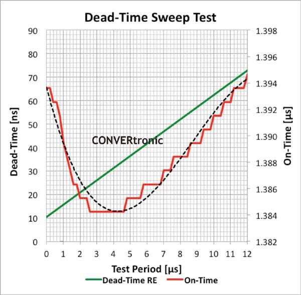 Figure 3 shows the results of a single sweep across a defined range of dead-time setting values during steady-state operation, measured on a test bench. The green line indicates the dead time applied to the rising edge of the switch on the high-potential side. The red curve shows the evolution of the switch's conduction time on the high-potential side for different dead-time values, while the black dotted line indicates its 3rd-order approximation.
The range for the dead time sweep is determined by characterizing the system and defining a most favorable case (shortest dead time) and a least favorable case (longest dead time). The sweep is performed with a maximum resolution of 4 ns for 90% load (Vin = 12V, Vout = 3.3V, Iout = 9A). On the left side of the graph, the duty cycle starts with values close to 1.394 µs and drops rapidly as the dead time increases. In this area, the high and low potential side switches already show some overlap, and some of the energy consumed from the input is conducted directly to ground.
For dead times of around 25 ns, the conduction time reaches its minimum of 1.384 µs and begins to increase again as the dead time is further increased. In a non-adjustable design, the dead time would have been set to at least 70 ns for the switches used, so the typical conduction time for this mode of operation would have been 1.395 µs. According to Equation III in Figure 2, the difference between the original and optimized conduction time on the high-potential side is 11 ns. At first glance, this doesn't seem like much, but in this high-frequency converter, it represents an increase of approximately 0.9% in efficiency, resulting in an overall efficiency increase from approximately 92% to 93%.
Adjustable Switching Frequency and Compensation Network:
A very attractive feature is the ability to adjust the compensation network and switching frequency via software. This not only simplifies basic setup but also allows for adjustments during operation. This has been, until now, the exclusive domain of fully digital controllers. In hard-switching topologies such as synchronous buck converters, switching losses are the primary cause of most power losses. To improve efficiency, especially for small loads, reducing the switching frequency can significantly improve the overall efficiency of the converter. However, when the switching frequency is reduced while the compensation network is fixed by hardware, the gains typically begin to drop, which can result in a loss of phase margin and gain. To compensate for this effect, it is necessary to adjust the system gains. The MCP19111 provides registers for adjusting the PWM generator ramp voltage, the zero frequency (resonant frequency at the origin, which defines the first pole), the total gain, the slope gain, and the slope itself. There are also register sets for adjusting the amplifier offset and current sensing gain. Although this technique may require a thorough system characterization process, it reveals the possibility of introducing significant improvements in efficiency and stability.

Efficiency Optimization with Very Small Loads:
In asynchronous buck converters, the power losses in the freewheeling diode are determined by the forward voltage drop multiplied by the current. Since there is a significant, permanent forward voltage drop across the diode that cannot be minimized, an additional switch with considerably lower voltage drops is often used to bypass/replace the diode, thus creating a synchronous rectifier. This technique is typically employed when load currents greater than 1 A are required. However, for small loads, when a low current flows through the switch on the low-potential side, the power required to drive the gate exceeds the savings achieved by bypassing the freewheeling diode with a switch. To achieve further efficiency improvements under these specific conditions, the MCP19111 offers a so-called diode emulation mode, which, when activated, disconnects the driver on the low-potential side. If the controller is disabled, the gate is no longer biased and the diode in the MOSFET structure will act as a rectifier, thus minimizing power losses.
This type of measure to minimize partial power losses and increase overall efficiency can be enhanced by Microchip's new MCP870xx family of power MOSFETs. This family of fast power MOSFETs with a low RDS(on) and a well-balanced factor of merit offers a range of on-resistance combinations relative to the total gate load to optimize the overall factor of merit of the half-bridge. The larger the QT of the switch on the low-potential side, the more effective the diode emulation mode of the MCP19111.
Optimizing No-Load Operation:
The MCP19111 is a current-mode driver designed to provide optimal performance during normal operation. However, a current-mode driver requires a minimum current flow to function correctly. When the load enters a low-power standby mode, the converter output must still supply the nominal output voltage, but the output power may be nearly zero. Current-mode drivers typically switch to some form of transient or pulse-frequency (PFM) mode operation with increased output ripple, which can exceed line regulation tolerances and often cause serious EMI problems. To overcome this limitation of typical current-mode drivers, the MCP19111 can be switched to a pseudo-voltage mode by disabling the current loop, resulting in improved output voltage and system stability.

Usability and Toolset:
The impressive list of advanced features of the MCP19111 offers an extraordinary number of options for configuring and optimizing the system. The microcontroller's open programmability adds even more degrees of freedom. Therefore, Microchip offers the Graphical User Interface (GUI) shown in Figure 4, which can be used to make certain adjustments and configurations without writing code. This GUI runs on open-source firmware that can be modified and used as a template for developing more advanced individual functions.
In addition to the configuration interface, Microchip offers a second GUI for test functions, allowing the user to establish direct communication with the device using the PMbus protocol (see Figure 5). This GUI works with Microchip's PICkit serial analyzer (Part Number DV164122), which is a low-cost, generic USB-to-UART/SPI/I²C interface and can be used directly to monitor and debug the device during operation.
Abstract:
Although most techniques are known and existing devices incorporate some functions, the MCP19111 family opens a new chapter in the history of intelligent switched-mode regulators. The density of dedicated functions, along with free programmability, makes a significant difference. In the world of intelligent power controllers, the MCP19111 brings both analog and digital control methods and eliminates existing limitations by making all functions available to the engineer, thus forming the basis for high-performance, innovative, efficient, and reliable POL converters.
Author:
By: Andy Reiter, Microchip Technology Inc.
 Andreas Reiter, Technical Director of Business Development for Power Electronics in Europe,
Microchip Technology
Andreas Reiter was born in 1973 and studied medical engineering and physics at the Munich University of Applied Sciences. From 2000, he worked as a development engineer and then as an R&D manager in the automation industry, before focusing on power electronics applications as an applications engineer in 2007. Since 2010, he has been responsible for application-oriented R&D of fully digital control methods and solutions in power electronics applications at Microchip Technology Inc.





