




 These applications range from portable highway signage and hazard warning lights in construction zones to remote pumping stations and communication towers. In fact, solar power is becoming a viable energy source for a whole new generation of off-grid applications.
There is always a reason why an application cannot be powered directly from the electrical grid: the equipment may need to be portable, such as highway signage or hazard warning lights in construction zones; or, as with power substations and telecommunications towers, its location may simply be too remote for the grid to access.
Some of the most critical design decisions for powering off-grid applications with solar energy are tied to the inherent advantages and disadvantages of the power supply system itself. These aspects will be determined primarily by the type of load and demand patterns, which are specific to each application.
Load Analysis.
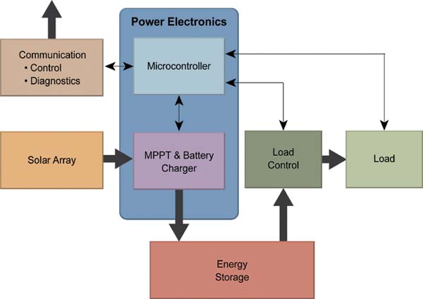
Figure 1 shows the block diagram of a high-level system that forms the basis for all solar energy designs. A thorough understanding of the main load characteristics and their behavior over time is essential at the beginning of the design process so that a balance between received, stored, and used energy can be achieved for each application.
 Loads come in different shapes and sizes: they can be constant or variable, day or night; and they can be intermittent or operate 24 hours a day, 7 days a week.
Analyzing the load type and behavior of each application load will determine the system's implementation. For example, hazard lights used in construction zones have a constant, pulsed, and nighttime load. This type of load can be charged during the day, and a battery size can be selected to ensure the hazard lights have enough power to operate all night. In contrast, a highway signal must have a pulsed load that operates both day and night. In this case, the battery and system must be sized to support a constant load during the day and simultaneously recharge the battery pack so the signal continues to function at night.
 A pump would also need to operate day and night, but its load would be more intermittent than constant. In this case, a system failure would need to be assessed, and the system would have to be designed to handle the worst-case scenario, including a backup system in case solar energy is insufficient to power the system. A rainwater pumping station, for example, would need a backup system because when it rains, there is very little sunlight to charge the batteries, and this is precisely when the system will be most heavily used: during or after the rain.
Each off-grid application will have its own type of load, but Figure 2 shows the load patterns for a hazard signal, a highway information sign, and a pump.
The key is to know the average daily load based on its magnitude and frequency, as well as its operating behavior. Once the load and its operating conditions are known, specifying the energy storage requirements becomes relatively straightforward.
Energy Storage:
The base energy storage requirement can be calculated using a simple energy balance method over a 24-hour period. Figure 3 shows the operating conditions and their impact on battery size. The energy storage capacity will be determined by the left-hand side of this table.
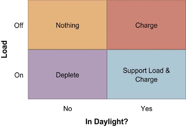 The load can be predictable, as in highway flashing lights, or highly variable, as in pumping applications. Managing variable loads involves two possible scenarios: normal operation, which covers 95% of cases, and worst-case operation, which covers the remaining percentage. Under normal conditions, the energy storage element can be recharged throughout the day and have enough storage capacity to power the load all night. However, in the worst-case scenario, the pump might start operating at dusk and run at full load all night. The following equation shows the worst-case energy storage requirement by consolidating the maximum hourly load energy over the period of time spent not charging.
Energy storage required = Maximum energy at the load per hour * (24 hours - Load time)
In the worst-case scenario, it is assumed that some energy remains in the battery or storage element, but the impact of not having a fully charged battery pack before operation should be considered.
In all applications, a major consideration is the impact and cost of a failure, such as the potential impact of a hazard warning signal not working or a pump not operating. One obvious technique for mitigating this is to increase the size of the energy storage element. However, there is always an absolute worst-case scenario. In situations where a failure cannot be tolerated, or where maximum power is rarely required, it may be possible to size the system for normal operation and add a backup system such as a diesel generator.
The left side of Figure 3 shows the energy storage requirements, while the right side can be used to size the solar array.
Solar Panel Sizing:
If the load requirements are thoroughly understood, the size of the solar panels can be adjusted. Based on Figure 3, the solar panels should be sized to cover the energy storage capacity within the specified load time, as well as to handle the average load output during that same period. This high-level relationship is defined by the following equation:
Solar panel output power =
Energy storage size +
Charging time
+ Average charging power
 Using a simplified energy balance technique, the size of energy storage components and solar panels can be estimated. However, other internal and external factors must be considered to refine the estimated dimensions.
One critical external factor is location, and more specifically, the latitude of the off-grid application. This alone will determine the peak level of solar exposure that can be expected, as well as its variation throughout the year. The minimum level of solar exposure will occur during the winter months, and the maximum exposure during the summer, due to the location's position relative to the sun.
Other external factors include cloud cover and ambient temperature, which can also adversely affect the amount of sunlight the system is expected to receive, as well as the efficiency of energy conversion. These external factors will necessarily vary with each application and location.
Internal factors, such as the system architecture and its interfaces, will also influence the size of the system components. In the previous examples, the size of the energy storage and solar panels determines the energy and power that could be supplied. However, since achieving 100% conversion efficiency is simply impossible, these unavoidable losses must be managed. This means that it is essential to consider power electronics when calculating the energy that needs to be generated.
 Power Electronics:
While the system block diagram in Figure 1 explains the energy balance, more information is needed to consider the internal factors influencing component size. Figure 4 provides further details on the system implementation and also includes questions that affect the power electronics strategy.
The power strategy is based on a microcontroller, providing inherent high-level flexibility. It allows the use of a standard reference design for a wide variety of applications, while also addressing specific application needs and adding advanced features. A microcontroller-based power design not only supports basic power conversion but also offers flexibility in selecting key components; it accommodates changes and allows for the optimization of different operating states. Furthermore, advanced functions such as communication and diagnostics, which would not be feasible for a dedicated standalone power converter, can be easily implemented using a microcontroller-based design.
In this implementation, the main questions are related to the load: what is the nature of the load and how will it be controlled? Will a voltage or current be required, and what will be the necessary accuracy of the current or voltage setpoint? Load control could be as simple as a relay or as complex as a three-phase inverter, but both require a charger function that uses solar energy to charge the energy storage device and, if possible, provides maximum peak power tracking (MPPT).
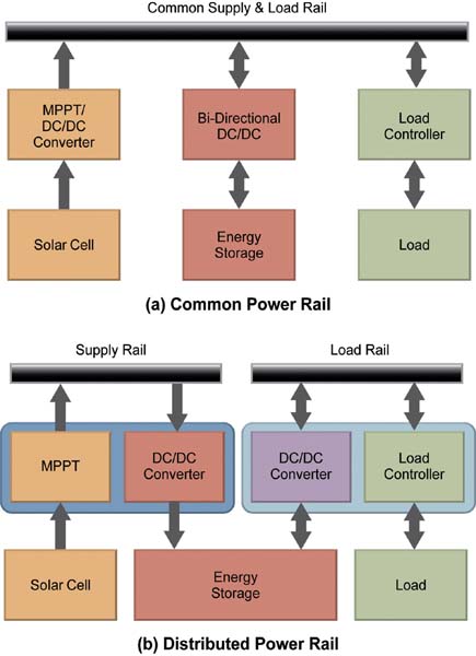
Perhaps one of the first decisions is to use a common rail or distributed power rail architecture. Figure 5 shows the difference between these architectures, although the load behavior will be the main factor influencing this design decision. If the load requires a constant voltage, the power rail shown in Figure 5a would be the best choice. In this case, the charge controller becomes a simple relay or solid-state switch. The solar DC/DC converter maintains the common rail at the voltage setpoint, and the battery charger is powered via the bus to charge the energy storage device. The advantages and disadvantages of this solution lie in the power conversion steps: assuming an average efficiency of 85% for power conversion, there will still be 15% conversion losses. If the solar DC/DC converter can handle the load, then it will be a single conversion step. However, battery charging requires two conversion steps to support the load: the first from the solar DC/DC converter to the common rail, and the second from the common rail to the bidirectional DC/DC converter. and the second from the two-way CC/CC to the common lane.
 A common rail can also be used if charging is only needed at night, when the solar DC/DC converter is not operating. In this case, the solar DC/DC converter can be eliminated, and the bidirectional DC/DC converter of the energy storage device can be used to charge the battery from the solar panels; or an alternative power source can be used to power the load. In this scenario, the energy requirements involve only two conversion steps: from solar DC/DC to bidirectional DC/DC, and from bidirectional DC/DC to the load.
The distributed architecture, shown in Figure 6, is more flexible and can handle diverse charging requirements. The solar DC/DC converter can be used, for example, to support energy storage for the load, while the DC/DC converter can be adapted to the load's requirements. The drawback of this option is that there are always two conversions, although it is the best solution if the solar panels and the load are expected to operate concurrently.
A Proposed Circuit Design
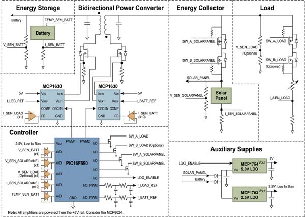
This high-level review of the power architecture can be applied to a simple, low-power example for hazard signaling used in construction zones. From a high-level perspective, the signalers operate only at night, and the battery will fully recharge them the rest of the time. This behavior allows the use of a common bus architecture, and since the hazard signalers are only charging or flashing, the topology can be simplified by combining solar DC/DC, bidirectional DC/DC, and load control into a single bidirectional converter. Figure 6 shows the proposed circuit design.
This circuit design uses a Microchip PIC16F690 microcontroller and two MCP1630 analog PWM controllers to control a bidirectional flyback converter. During the day, solar power is used as input to charge the battery; when nighttime is detected by a "low or no power" warning on the solar panel, the converter begins supplying power to the LED using a programmed flashing pattern. The assumptions and calculations underlying this design are summarized in Table 1.
Conclusions:
The lower cost of solar installations will allow more off-grid applications to access solar energy. The success of these new solar energy systems will depend on the balance between advantages and disadvantages, size and cost, as well as the use of an appropriate topology for each end application.
 Using a microcontroller as the basis for energy conversion provides a high level of flexibility. It not only supports a wide range of end applications based on a standard reference design, but also ensures the design's future viability as the next generation of photovoltaic solar technology develops.
Author:
By Stephen Stella, Director of Product Line Marketing, Analog and Interface Products Division, Microchip Technology Inc.





