Illuminating an entire group of LEDs simultaneously to achieve maximum brightness may be impossible in low-power applications due to the limited current supply. To produce optimal brightness, the power dissipation for each LED from the low-power source must be efficiently managed. This requires a power management technique in which, within the LED group, only one bank of LEDs is powered for a specific period. The other banks of LEDs will not be visually detectable while the required brightness is being achieved.
The available power and the required luminous intensity for the application must be determined in order to calculate the number of LEDs needed for a given time interval. A comparison between the luminous intensity and the DC current characteristics should be made to select LEDs with the required intensity level. Once the required number of LEDs is established, this number can be powered for a time interval determined by the ratio between the total current required by the LEDs and the available current, as follows:
Number of LEDs in a bank = Total current required by the LEDs / Total current available from the source.
The switching frequency of the LED bank must be adjusted so that the ON time is long enough to fully illuminate the bank, and the OFF time is limited by the time it takes before the bank begins to dim visibly. The OFF time limits the number of additional LED banks that can be controlled by managing the time interval.
This technique can be implemented at low cost using a clock source, digital flip-flops to control LED banks, and an OR gate to detect a start-up state with a simple On/Off switch. Figure 1 shows the block diagram of a D flip-flop configuration for controlling four LED banks.
 Initially, the flip-flop is in a static state and requires a trigger pulse that must last at least one cycle. This pulse can be detected by the first flip-flop on the rising edge of the clock. The trigger signal must be momentary and cannot last longer than one clock cycle; otherwise, the first two outputs of the flip-flop will be set simultaneously. Since the current supplied is limited, the lighting application will not function correctly. With this configuration, a bank of LEDs is fully illuminated on the rising edge of each clock cycle, and to the human eye, it appears as if all the LEDs are fully illuminated at once.
However, this implementation is monotonous and offers no design flexibility. It only has an on/off state. This circuit might be suitable for applications like LCD backlighting, but if you need to dim or generate sequences, a microcontroller-based circuit offers maximum flexibility with minimal impact on the overall cost of the solution. The circuit construction is simpler, requiring fewer components, since the microcontroller controls each LED bank and can also detect user inputs for dimming control and sequence selection.
A low-cost, low-pin 8-bit microcontroller, such as Microchip's PIC10F or PIC12F family, paired with an I/O port expander like Microchip's MCP23018, would offer an economical solution. I/O expansion can also be useful for controlling LEDs when the lighting circuit is located remotely from the microcontroller.
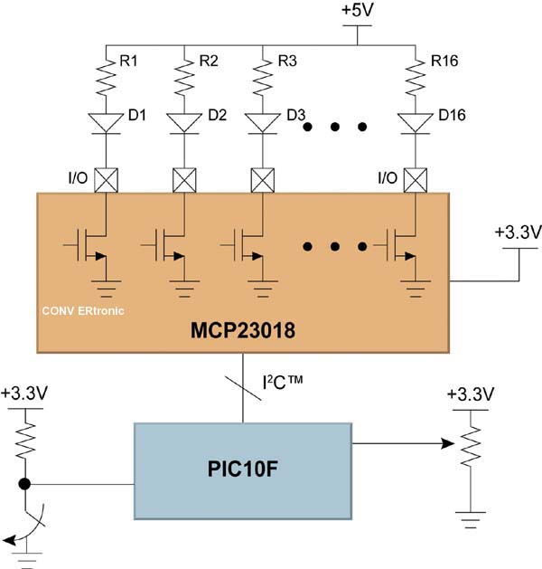 I/O port expanders extend the I/O ports of a microcontroller. In this application, the microcontroller controls the I/O expander using the I2C™ protocol to turn LEDs on/off. The microcontroller's I/O pins can be used to sense user input via a push button or a built-in A/D converter to sense a potentiometer level for dimming control.
I/O expanders are available in open-drain or push-pull output configurations. Microcontrollers can operate at 3.3V or lower, so an I/O expander with an open-drain output is well-suited for this application. The advantage is that it allows LEDs to operate at 5V or higher, provided the microcontroller and I/O expander are powered at a lower voltage. The MCP23018 is a 16-bit I/O port expander with an open-drain output and an I2C interface. Figure 2 shows the circuit diagram for an I/O expander with an open-drain output boosted to a voltage higher than the microcontroller's supply voltage.
When the I/O port is set low, the voltage across the I/O amplifier is 0V, and current flows, forward-biasing and switching the LED to conduct. The LED bias resistor limits the current to the LED according to the required brightness and also acts as a pull-up resistor for the open-drain output.
When the I/O amplifier's output port is set high, the open-drain output goes into cutoff or high impedance, and the voltage at the I/O amplifier port is raised to 5V by the pull-up resistor. The LED is in cutoff because no current will flow. An open-drain configuration also offers the advantage that, when the port is set to high impedance, it takes longer to turn off the LED due to parasitic capacitance. This allows the next bank of LEDs to conduct for a slightly longer time compared to similar push-pull output applications.
The MCP23018's 16 I/O ports can control up to 16 LEDs. The amount of current that can be supplied to the I/O port when the LED is fully conducting can be limited by controlling the I/O amplifier output. The I/O port's low-level voltage is specified up to a maximum of 0.6V for a current of 8.5mA. If the current exceeds 8.5mA, the low-level voltage will increase exponentially. The absolute maximum current is 25mA.
If the supplied current is limited to 5V/50mA, for example, and 2mA is allocated to the microcontroller, the I/O expander, and the resistors for user input detection, the remaining available current can be used for LED illumination. Four LEDs per bank can be driven if the LED's luminous intensity at approximately 10mA is adequate. In this example, the current-limiting resistor would be rated for approximately 440Ω.
void main (Void){
initialize(); //initialize the PICmicro peripherals including Timer0, and I/O expander peripherals
bank_counter = 0; //Clear the bank counter variable
while(1){} //infinite while loop
}
Void Interrupt int_service(void){
TurnOffAll_LEDs(); //subroutine to turn off all previously lit LEDs
I2C_start(); //I2C protocol – start signal subroutine
I2C_send(Comand_byte); //I2C protocol – send byte subroutine
If(bank_counter == bank1){ // bank1 is a constant defined as 0
I2C_send(Address_pionter_bank1n2); //Send peripheral register address pointer
I2C_send('0000 1111'); //I2C protocol – send bank status (bank 1 on and bank 2 off)
bank_counter = bank_counter + 1;
}
If(bank_counter == bank2){ // bank1 is a constant defined as 1
I2C_send(Address_pionter_bank1n2); //Send peripheral register address pointer
I2C_send('1111 0000'); //I2C protocol – send bank status (bank 2 on and bank 1 off)
bank_counter = bank_counter + 1;
}
If(bank_counter == bank3){ // bank1 is a constant defined as 2
I2C_send(Address_pionter_bank3n4); //Send peripheral register address pointer
I2C_send('0000 1111'); //I2C protocol – send bank status (bank 3 on and bank 4 off)
bank_counter = bank_counter + 1;
}
If(bank_counter == bank4){ // bank1 is a constant defined as 3
I2C_send(Address_pionter_bank3n4); //Send peripheral register address pointer
I2C_send('1111 0000'); //I2C protocol – send bank status (bank 4 on and bank 3 off)
bank_counter = 0;
}
I2C_stop(); //I2C protocol – stop signal subroutine
}
Pseudocode 1: Microcontroller interrupt service routine code
*
*
*
If(bank_counter == bank1){ // bank1 is a constant defined as 0
I2C_send(Address_pionter_bank1n2); //Send peripheral register address pointer
Bank1n2_pattern = ~Bank1n2_pattern; //complement the variable using '~'
I2C_send((Bank1n2_pattern | '0000 1111')); //I2C protocol – send bank status
//(use OR '|' to set bank 1 on and bank 2 off)
bank_counter = bank_counter + 1;
}
*
*
*
Pseudocode 2: Sequence generation.
*
*
*
Void Interrupt int_service(void){
TurnOffAll_LEDs(); //subroutine to turn off all previously lit LEDs
If (Delay_ON == ON){ // ON is a constant defined as 1
Update_Timer0_Counter(Timer0delay_interval); //subroutine to update Timer0
// Timer0delay_interval is a constant to set the minimum delay
Delay_Counter = Delay_Counter – 1; //count down the number of interrupts for delay
If(Delay_Counter == 0){
Delay_ON = OFF; // Clear the delay flag for the next interrupt
Delay_Counter = Get_Delay_Counter(); //subroutine to detect user input
//and set the delay counter variable
}else{
Delay_ON = ON; // leave delay flag ON
Return; //exit the interrupt service routine
}
}
I2C_start(); //I2C protocol start signal subroutine
I2C_send(Comand_byte); //I2C protocol – send byte subroutine
If(bank_counter == bank1){ // bank1 is a constant defined as 0
I2C_send(Address_pionter_bank1n2); //Send peripheral register address pointer
Bank1n2_pattern = ~Bank1n2_pattern; //complement the variable using '~'
I2C_send((Bank1n2_pattern | '0000 1111')); //I2C protocol – send bank status
//(use OR '|' to set bank 1 on and bank 2 off)
bank_counter = bank_counter + 1;
delay_ON = ON; // turn on the delay flag
}
*
*
*
Pseudocode 3: Implementation of the delay code to visualize a lighting sequence.
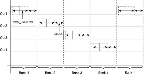
The timing diagram shown in Figure 1 can be reproduced using a short microcontroller instruction code. For example, for Pseudocode 1, the main subroutine could be an infinite while loop. For each microcontroller time interval (Timer0), an interrupt service routine sends an I2C instruction to the I/O expander to drive only one LED bank. The interrupt service routine counts or tracks the status of the LED bank, such as whether the bank is currently conducting, and the configuration of the corresponding I/O expander port as high or low. Initially, or after the microcontroller resets, bank 1 is turned on at the first Timer0 interrupt. At the second interrupt, bank 1 is turned off and bank 2 is turned on. Then, at the third interrupt, bank 2 is turned off and bank 3 is turned on. Finally, on the fourth interrupt, bank 1 is deactivated and bank 4 is active, and the bank counter variable is reset to zero. On the next interrupt, the cycle repeats, activating bank 1 and deactivating bank 4. Other variables, such as Command_byte, Address_pointer_bank1n2, and Address_pointer_bank3n4, are constants defined in the startup file. In this type of implementation, the circuit generates the necessary light intensity, and it appears as if all the LEDs are being activated simultaneously by the available power supply.
Void get_PWM_ratio(void) {
Double PotScale; //local variable to store ADC output scale
Double PWM_Percentage; //local variable to store PWM change percentage
PotScale = (ADRESH)/16 + 1; //Scale ADC output high byte
PWM_Percentage = 1/16 * PotScale; //Scale the output from from 0 to 1, equivalent to 100%
PWM_High = Frequency_counter * PWM_Percentage; //set PWM high Timer0 value
PWM_Low = Frequency_counter * (1 – PWM_Percentage); //set PWM low Timer0 value
//PWM_High and PWM_Low are global variables,
//and Frequency_counter is a constant Timer0 value to set frequency.
}
Pseudocode 4: Subroutine to calculate the PWM ratio
*
*
*
If(bank_counter == bank1){ // bank1 is a constant defined as 0
If (PWM_High_Low_flag == OFF){ //check PWM status flag
get_PWM_ratio(); //Detect user input for PWM ratio
Timer0_counter = 65535 – PWM_High; //set Timer0 counter variable
Update_Timer0_Counter(Timer0_counter); //subroutine to update Timer0
I2C_send(Address_pionter_bank1n2); //Send peripheral register address pointer
Bank1n2_pattern = ~Bank1n2_pattern; //complement the variable using '~'
I2C_send((Bank1n2_pattern | '0000 1111')); //I2C protocol – send bank status
//(use OR '|' to set bank 1 on and bank 2 off)
PWM_High_Low_flag = ON; //Set flag
Delay_ON = OFF;
}else{
Timer0_counter = 65535 – PWM_Low; //set Timer0 counter variable
Update_Timer0_Counter(Timer0_counter); //subroutine to update Timer0
I2C_send(Address_pionter_bank1n2); //Send peripheral register address pointer
I2C_send('1111 1111')); //I2C protocol – turnoff all LEDs
bank_counter = bank_counter + 1;
PWM_High_Low_flag = OFF; //Clear flag
Delay_ON = ON;
}
}
*
*
*
Pseudocode 5: Code flow to adjust the PWM ratio.
Dimming control and LED sequence generation.
Interesting light sequences can be generated with a microcontroller-based application. The output states of the I/O port expander are loaded from
2 bytes of variables in RAM named Bank1n2_pattern and Bank3n4_pattern. The half byte corresponds to each bank. A predefined lookup table contains several sequences of ones and zeros for each bank.
 To continuously monitor the on/off button's state, an IF THEN instruction is added to the microcontroller code: the infinite 'while' loop of the main subroutine. When the button is momentarily pressed, a sequence is loaded from the lookup table into the two bytes of RAM, named Bank1n2_pattern and Bank3n4_pattern. When the Timer0 interrupt occurs, the new sequence is sent to the I/O expander, and the LEDs light up according to the sequence. The main subroutine iterates through the lookup table as long as the button is momentarily pressed by the user. To display another lighting sequence, simply send the complement of the previous sequence. For example, if the sequence in bank1 is '0101', the complement is '1010', as shown in Pseudocode 2, which is a snippet of Pseudocode 1.
However, a delay must be added to the interrupt subroutine before the IF THEN instructions for bank on/off visually inspect the alternate sequences. This is generated by a Delay_ON flag, so that in the next interrupt, only the delay counter is subtracted to count the number of interrupts for the delay. The user can also select the delay value with a potentiometer whose terminal would be connected to the input of the A/D converter integrated into the microcontroller. The digital data from the A/D converter is scaled from a minimum to a maximum delay by detecting the four upper bits, which provide 16 levels. A more precise adjustment can be made by detecting the five upper bits, i.e., 32 levels. The maximum delay is the slowest rate at which the LEDs can blink, and with a minimum delay, it appears as if all the LEDs are on. Figure 3 shows the position of the delay, tDELAY.
To control the duration of the time interval for each bank, the dimming control uses pulse width modulation (PWM). The Timer0 interrupt duration has two values, a long duration and a short duration, proportional to the PWM percentage adjusted by a rotary potentiometer whose center terminal is connected to the input of the A/D converter. The resolution level can be adjusted by selecting the upper 4 or 5 bits of the A/D converter. The Timer0 counter position is adjusted proportionally to and on a scale of the A/D converter data, where 100% PWM corresponds to the maximum counter position (fully illuminated), and 0% is the minimum or lowest dimming level. Pseudocode 4 shows the PWM scale equation for 16 levels, and Figure 3 shows the timing diagram during PWM, tPWM_LOW, and tPWM_HIGH.
The interrupt service routine must update the Timer0 counter position for the next interrupt. It must also detect whether the PWM signal is long or short. Therefore, a few instructions must be added to detect the potentiometer level for dimming control and proportional scaling of the Timer0 counter position using the PWM_High and PWM_Low values shown in Pseudocode 4. Pseudocode 5 shows the code for adjusting the PWM; an IF THEN instruction is used to detect the PWM state.
This methodology can also be implemented on a mid-range 8-bit microcontroller with added program memory, such as Microchip's PIC16F family. An upgrade would allow the main subroutine to handle advanced lighting sequences, such as continuous-motion lights. The microcontroller's Timer1 module can be used to vary the duration, and the two bytes of RAM are updated for the continuous-motion sequence.
Designers are always looking for new ways to reduce costs without compromising performance. Numerous methods exist for efficiently controlling LED banks used in LCD backlighting or lighting sequence applications for efficient illumination. In low-power applications, LEDs can be controlled by managing the timing interval for each LED bank. Furthermore, low-pin microcontrollers and I/O port expanders offer a low-cost alternative for lighting solutions with greater design flexibility.
Author:
Ezana Haile, Chief Applications Engineer, Analog and Interface Products Division, Microchip Technology Inc.