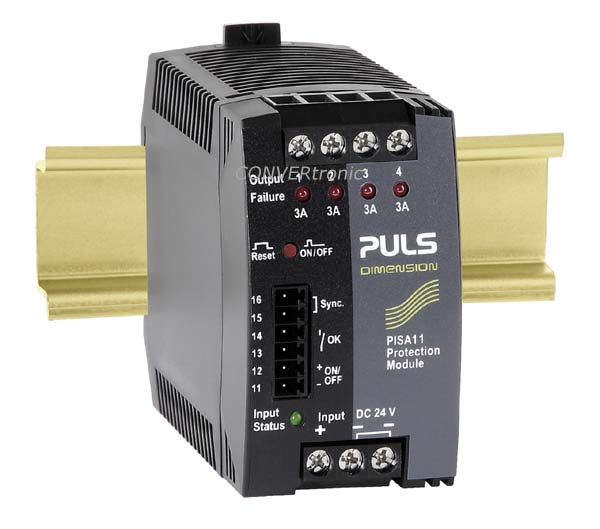
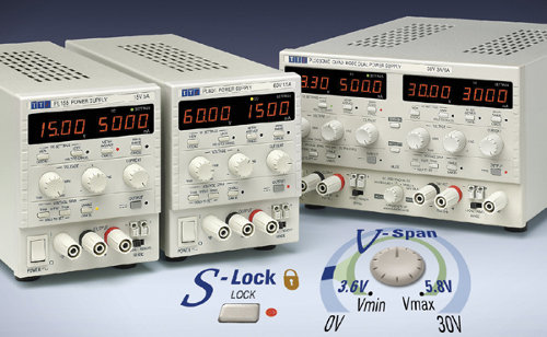
Figure 1: Parallelization
• Redundancy: Connecting several power supplies in parallel so that if one supply fails, the others continue to power the connected load. It is necessary that if one power supply fails, the others can take over the power of the connected loads. We can have 1+1 redundancy (if one supply fails, another continues to supply the entire load) or N+1 redundancy, which allows for N failures.
 Figure 2: 1+1 redundant system
Figure 3: N+1 redundant system
Recommendations for Parallelization or Redundancy:
We must adjust the output voltages to a value as similar as possible. The length and cross-section of the cables must be the same to ensure the same voltage drop in both cases. (PULS power supplies have potentiometers that allow for very precise adjustment of the output voltage, facilitating parallelization.) The Dimension series has multi-turn potentiometers (15 turns) that allow for precise adjustment of the output voltage.
Ideally, the output voltages should be adjusted according to the load each supply must handle (the voltage drop across the cables depends on the current flowing through them).
We should only parallel power supplies from the same series, meaning those with identical output characteristics. It is recommended that they be of the same model. You can consult the power supply specifications or contact our technical department.
Common Problems with Parallel Connections:
If we connect both power supplies and turn them on, when we measure the output voltage of each supply, we are actually measuring the output voltage of the one with the highest voltage, unless we have diodes to isolate the voltages.
Temperature affects the resistance of the cables and their internal resistance (see the power supply's temperature coefficient).
If one power supply is at a significantly higher temperature than the other, the output voltages will not be exactly the same or will vary depending on how hot one supply gets. Special care must be taken when connecting power supplies in parallel in high ambient temperatures.
Load Sharing and Problems:
Ideally, in parallel or redundancy, the power supplies should share the workload. This reduces stress on the power supplies by preventing one from handling all the work, thus lowering the power supply's temperature and increasing its lifespan.
A common problem with redundant connections is the lack of diodes. In this case, if one power supply turns off or on before the other, the output of one supply may interfere with the output of the other and damage it.
PULS offers redundant power supplies with built-in diodes (SLR SilverLine Redundancy series) or diode modules for external connection. All PULS power supplies are capable of absorbing significant reverse voltage thanks to their output capacitors, so in many cases, these diodes are not necessary. For example, PULS power supplies with a 24VDC output typically support reverse voltages of up to 36VDC.
 Problems with Redundancy:
If diodes are not used in a redundant application and one power supply fails, shorting its output, this power supply will act as a load on the other. In this case, the system will shut down, even if there is still a working power supply.
Fig. 4: Operation in case of failure of one of the power supplies with a short circuit in the secondary; the system shuts down because there are no diodes.
It is not recommended to place one power supply on top of another. The heat from one will heat the other. We must maintain a separation distance between them, according to the manufacturer's specifications (usually 40mm above, 20mm below, and 15mm on the sides).
If the power supplies do not have diodes, the LEDs and alarm signals may be false. The OK LED is usually powered from the output terminals, so if the voltage from one power supply enters the output of the other, the LED will light up, even if it is off.
Parallelization Methods There are different ways in which we can make power supplies connected in parallel/redundancy share the load:
• By adjusting the output voltage. Whenever we parallelize, we must adjust the output voltages to values as close as possible, and in no case should there be a difference of more than 0.5V DC.
Figure 5: Voltage Adjustment
• Synchronization between power supplies so that they provide the same output voltage (parallelization terminals are necessary). Some manufacturers offer the option to connect multiple power supplies with a single cable. This allows for fairly precise adjustment of the output voltage.
Figure 6: Model SL40.301 has a current sharing function
. • “Smooth” output voltage versus current characteristics. This system means that the power supply's output voltage decreases as the load increases. The output voltage is not always the same. If one power supply has the highest output voltage (which is the one that will normally supply all the output current), as more current is demanded, its output voltage decreases, and therefore, at some point, the other power supply will begin to take over part of the load.
 Figure 7: Normal curve vs. Smooth curve
• Intelligent Output Power Control (Q-Dimension Series). The Q-Dimension series features intelligent output power control. The power supplies can operate for a period of time above their rated power (Bonus Power). After this time, the controller limits the power supply's output power by reducing the output voltage (constant current) while maintaining the output current at the maximum permissible value for the power supply. This ensures the power supply operates safely. By reducing the output voltage according to the connected load, the other power supply will then take over part of the connected load.
Figure 8: QT40.241 model from the DIMENSION family with intelligent control
Author: OLFER Electronics Marketing Department