

Current transducers used in PV inverters must follow these trends: they must be compact and offer equivalent or better performance at a lower cost compared to the transducers they replace. PV installations typically use current transducers at three points. One is located on the DC side for the maximum power point tracking (MPPT) system. The other two are located on the AC side: the first to define the output current waveform parameters and the second for safety reasons to measure residual current (RCM) at the output, which is generated by earth leakage and can cause the system to shut down if necessary. This article presents a new compact transducer specifically designed for measuring residual current.
1. INTRODUCTION
 Figure 1 shows the main components surrounding the inverter in a PV system typically used in residential installations up to approximately 20 kW. Several inverters of this type can be combined to create a complete system, which is connected to the electricity grid via meters.
 Figure 2. Residual voltages and currents in the PV installation.
Over the past decade, new silicon MOSFETs have been incorporated into inverters, and in the future, SiC- and GaN-based MOSFETs will begin to replace silicon-based ones. This allows for increased switching frequencies, which in turn reduces the size of reactive components (inductors, capacitors), and therefore their dimensions. A 2kW inverter available in 2010 weighing 20 kg, according to the manufacturer's specifications, was replaced in 2016 by a model weighing less than 10 kg. To ensure that current transducers used as measuring devices in a PV system continue to represent a negligible portion of the total space and weight, their size must also be reduced without compromising performance. Similarly, their cost must also be reduced to follow the downward trend of the inverter system as a whole.
 The figure shows three LEM current transducers, all of which contain custom-designed proprietary CMOS ASICs with fully integrated Hall effect cells. On the DC side of the inverter is an open-loop GO; on the AC side, a closed-loop LPSR for the inverter control system; and at the output, a closed-loop LDSR, a new differential transducer for the RCM. (For a detailed explanation of the open-loop and closed-loop Hall effect transducers, see Reference (1))
Figure 2 illustrates the voltage waveforms on the DC and AC sides of the inverter. Note that in a transformerless system, the "DC side" does indeed have a DC voltage corresponding to the output of the photovoltaic cells between the PV+ and PV- nodes (this may need to be boosted with a DC/DC converter), but each PV node also has an AC voltage whose peak value is similar to the peak output voltage on the AC side. If this is not taken into account at the system level, it represents a serious safety issue.
2. Measurement of residual current for safety.
The PV+ and PV- nodes in Figure 1 are large in a typical PV system. The average voltage at each node, referred to ground, is half the voltage across the PV cells, but it also contains an AC voltage with a peak value similar to that of the cells. If a person touches the PV+ or PV- nodes (or, in general, any node on the DC side of the inverter), a leakage current will flow between the system and the person, and to ground. Since there is only one node in the system whose potential is maintained at ground level—the output node N—this leakage must return to the system through node N, causing a DC current imbalance, or residual current, between the L and N outputs. This residual current must be detected to allow the system to respond as quickly as possible to protect the person who caused the residual current. Among the challenges involved in RCM, the following stand out:
i) The absolute value of the current to be detected is low, on the order of a few tens of mA, and therefore the transducer offsets must be sufficiently low to detect this current level;
ii) The AC output current has a value between zero and tens of A, and the residual current must be detected in its presence;
iii) The capacitance between the PV panels and ground means that there is always a current flowing to the ground connection, and the objective of the system is to distinguish this from an added current caused by dangerous human contact.
Figure 2 shows the leakage current path in a simplified inverter system with the new LEM LDSR transducer used for RCM.
Of the three points mentioned above, (i) and (ii) have been achieved with LDSR thanks to a special design for RCM, while (iii) is achieved by applying a signal processing algorithm to the transducer output.
Figure 3 shows the basic structure of RCM: an ASIC with a Hall cell, similar to that used in the LPSR transducer, occupies the center of a closed-loop transducer. The AC currents I1 and I2 cancel each other out, and the low residual current is detected by the Hall cell ASIC and compensated in the secondary winding, which has far fewer turns than the LPSR since the current to be detected is much lower.
Figure 3: Operating principle of RCM based on Hall effect closed-loop technology.
Detailed analysis of the primary conductor position in Figure 3 indicates that the cancellation of I1 and I2 is not perfect, and the residual magnetic field in the air gap depends on their position. Therefore, it was decided to precisely define the primary conductor positions, and for this purpose, a multilayer printed circuit board was chosen within the transducer. Furthermore, RCM only requires a few dozen turns in the secondary coil, meaning these can also be etched onto a printed circuit board. This results in an innovative sensor with a much simpler construction than other closed-loop sensors. While placing the primary conductors on a printed circuit board limits the maximum current in the primary, the feasible value of 35 A per conductor is more than sufficient for domestic installations.
For testing purposes, an additional coil is wound on the ASIC's printed circuit board concentric with the secondary circuit. This is useful for system testing: the current flowing through it will provide a transducer output in the same way as the current difference between the primaries.
Like the LPSR transducer, the ASIC is designed to have minimal offset, and the offset related to the input current is reduced by placing a hole in the printed circuit board under the ASIC, thus making the air gap as small as possible in the magnetic circuit.
Due to the high sensitivity of the LDSR, magnetic shielding is placed around the ASIC and the air gap.
 Figure 4 shows a photograph of the LDSR transducer.
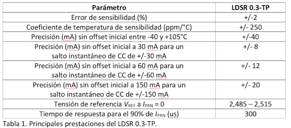
In general, leakage currents detected by the LDSR will have both AC and DC components, and each user will employ a specific algorithm at the transducer output to determine when leakage is "excessive" and to take appropriate action. A particularly challenging scenario arises when there is a large, naturally occurring, and variable AC leakage component (depending on ambient humidity, for example) due to parasitic capacitances, and the highest level of leakage caused by a person touching the DC side must be detected. The impedance presented by a person is highly resistive, so, as shown in Figure 5, the added current is practically equal to the RMS value of the leakage current; the main effect is a phase shift.
 Figure 5: Effect after adding a resistive path to the leak.
There is also, of course, noise that adds to the real and imaginary currents in Figure 5. If only one frequency is known, it must be analyzed using a sampled waveform; the Goertzel algorithm is very efficient. In Figure 6, a 30 mA rms "person leakage current" is added to a 300 mA rms "capacitive leakage current" with 7.5 mA rms of noise after 0.1 s. The visible effect on the total leakage current is quite imperceptible, but after processing with the Goertzel algorithm, the current is easily recovered to 30 mA. If this value exceeds a predefined threshold, appropriate system-level measures can be taken.

Figure 6. Simulation of residual current during a fault and output of the Goertzel algorithm.
Conclusion
This article uses the example of photovoltaic installations to illustrate the recent advancements in LEM current transducers for measuring residual current. Their size and cost have been reduced while their performance has been maintained or improved. The transducers are now designed without the previously required magnetic induction component. This innovation is possible because the design complexity of the transducer has been transferred to the custom Hall-effect ASICs they utilize.
Reference (1): https://www.lem.com/en/file/3139/download