

Furthermore, fully electric vehicles saw a 44% year-on-year increase and accounted for 16% of all cars sold in Europe.<sup>1</sup>
These figures are positive for all vehicle manufacturers after the dismal sales recorded during 2020-2021 due to the COVID-19 pandemic. The recovery in overall sales and the significant growth in EV sales bode well for the future. Consumer concerns regarding charging infrastructure and battery range remain. In response, manufacturers already have second-generation EV models in production that address these concerns.
Trends Characterizing the Second Generation of EVs:
Several trends are worth highlighting.
1. Improved charging time and reduced vehicle weight. Weight directly impacts an EV's range. Therefore, any reduction in vehicle weight increases its payload and maximum range.
2. Eliminating the traditional 12VDC primary battery is highly advantageous in terms of weight. It is now possible to reduce its size or even remove it altogether.
3. Adopting a 48V zonal architecture reduces the need for bulky, heavy, and expensive wiring. Implementing a 48V architecture for secondary equipment (heated seats, seat adjustment, etc.) also benefits from reduced cable size and weight.
4. The increase in battery voltage from 400V to 800V is happening rapidly. This trend allows for reduced cable weight and charging time but requires modernizing the charging infrastructure to supply both voltages.
It is also necessary to introduce other significant improvements in safety and reliability. Since the EV draws all its power from a single source, such as the high-voltage traction battery, any interruption is inevitably problematic and could threaten safety. Therefore, while conveniences may attract consumers and boost sales currently, the long-term viability of EVs depends on the stringent safety protocols incorporated into the vehicle. In a fully electric car, redundant power supplies are paramount.
Designing a redundant power supply is essential for safety and reliability.
Incorporating a redundant power source into an EV ensures safety and reliability for the driver, passengers, and other road users. Redundant power is necessary for three types of loads:
• Steering, braking, and safety sensor systems
• Continuous communication via the vehicle network (CAN bus, Ethernet, etc.)
• Non-essential loads must be disconnected during critical power situations
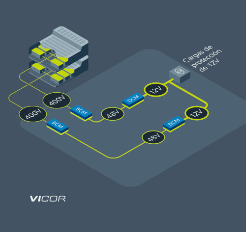
. For example, EV power architecture designers could create an 800V traction battery source by connecting two 400V batteries in series, with each battery configuration having a separate DC/DC converter (400V to 800V). This configuration (Figure 1) is called a series-stacked dual 400V system.

Figure 1. Dual 400V system stacked in series. Connecting two 400V batteries in series, with separate DC/DC converters in a stacked architecture, operates at a lower voltage and divides the load into two or more parts (Source: Vicor)
Some manufacturers are already using the dual 400V series-stacked system for several reasons. The main reason is that charging is easier with a 400V charger because many of the installed public chargers do not support 800V. However, newer chargers being installed are compatible with both 400V and 800V batteries. The second reason is that if a manufacturer has already designed and certified a 400V battery, it is quicker and simpler to add two in series.
Another method is the dual 800V parallel battery configuration (Figure 2), which involves using two 800V batteries in parallel. Again, two separate DC/DC converters provide redundancy.
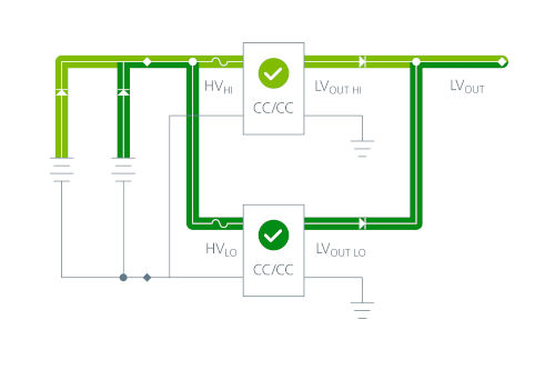
Figure 2. Dual 800V battery configuration in parallel. This configuration operates at a lower current and is a simpler method for implementing N+1 redundancy (Source: Vicor)
Both configurations have advantages and disadvantages.
These are the disadvantages when using a dual 400V system stacked in series:
• The 400V DC/DC converters need more clearance to the case ground because the upper DC/DC converter is rated at 800V.
• The center tap between the two 400V batteries must be accessible at the high-voltage connector.
• An imbalance between the two 400V batteries connected in series can cause the regulator to enter overvoltage protection mode and cut off power.
These are the advantages of the system:
• If one row fails, the other will take over the load.
• The system components operate at lower voltages and are therefore less expensive.
• It is easier to create a 24V output by connecting the two outputs in series.
The dual 800V battery configuration in parallel also has advantages and disadvantages.
Advantages:
• Offers greater stability than with 400V
. • Is easier to charge because the parallel configuration sees the full 800V supply. In a parallel configuration, the batteries have the same voltages, hence it is less complicated to charge.
Disadvantages:
• From a design perspective, the components require more clearance from the casing for safety against high voltage.
• A short circuit at the 800V potential will shut down the entire system.
While relatively few vehicles currently use an 800V dual-battery platform, the redundancy it offers is important for safety. Without it, the car's most critical systems are just one short circuit away from catastrophic failure. EV power architectures are moving in this direction. Reliability and safety are the main reasons for this evolution, but new chargers are compatible with both 400V and 800V, indicating the market trend towards 800V.
Several factors can influence the choice between one configuration or the other, but in most cases, the 800V dual-battery configuration is preferable for one simple reason: in this system, the power modules facilitate the incorporation of redundancy because the batteries are connected in parallel. This allows for a secondary connection to the load in case of a short circuit, thus protecting the system from complete shutdown.
Weight and operating time must be considered, as well as the physical space required to install two batteries. While additional circuitry is needed for the battery management systems, the increased safety and reliability more than compensate for this.
The Many Faces of Redundant Power Supply: Which Is Best?
Redundancy can be implemented in several ways (Figure 3). The load can be shared by two or more DC/DC converters, and a single converter can take over the entire load if one of the power supplies or converters fails. Designing a robust and reliable power architecture for an electric vehicle is a complex task. However, thanks to redundancy, manufacturers can improve vehicle safety and reliability, and more importantly, consumer confidence.
Redundancy can take many forms. Let's look at the entire power chain from the source to the load and ask ourselves: If a failure were to occur at this point or in this part of the circuitry:
• What would it affect?
• Would the vehicle continue to operate?
• Which functions would be disabled?
The goal is to ensure that the journey continues or that it is possible to safely leave the road.
Redundancy in a DC/DC converter can take several forms (Figure 3), such as N + 0, N + 1, 2N + 1, etc. Each configuration has advantages and disadvantages in terms of size, cost, and complexity. Detailed analysis of the operation for each vehicle's architecture is necessary.
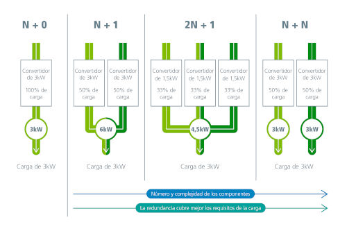
Figure 3. Various combinations of redundant architectures with their power levels and power supply structures in an EV propulsion system. The N+1 configuration achieves higher power and can therefore be a larger and more expensive solution. From left to right, redundancy improves and the power supply better meets the load requirements, but it also increases the number of components and the system's complexity. (Source: Vicor)
Using a bidirectional DC/DC converter and separating the vehicle's loads allows power to be transferred from one area to another. When this is done with a regulator, a reliable power source is obtained to supply the load or even charge a battery.
However, current power converter technology is not yet capable of making DC/DC converters small and light enough to install multiple units in parallel in EVs.

Figure 4. This 4kW DC/DC converter uses two Vicor BCM6135s and two DCM3735s (installed on the underside of the board) to convert 800V to 12V in a unit weighing 0.08 kg and with a volume of only 0.8575 l. It can be configured as two redundant 2 kW power supplies or in parallel with another unit to create a redundant 4 kW power supply.
Vicor's BCM® and DCM™ power modules facilitate parallel connection. Their small size reduces the overall size of the DC/DC converter, while their efficiency and density boost performance (Figure 4). This, in turn, increases vehicle range and allows for new architectures that improve safety.
High-density power modules open up creative opportunities and offer significantly higher levels of performance and scalability compared to discrete solutions. Power modules can triple the power density, facilitate scalability, and handle faster transients, allowing for a reduction in structure or the elimination of the 12V/48V auxiliary battery. The BCM (Figure 5) reduces the voltage on the high-potential side and multiplies the current, while also providing isolation in a highly efficient, high-power-density converter.

Figure 5: BCM® bus converter. BCMs are high-density, high-efficiency, fixed-ratio (non-regulated) isolated DC/DC converter modules. This family of devices supports 800V or 400V to 48V inputs with various K-factors to cover a wide range of applications. The BCM provides the highest power density for converting high-voltage batteries to low-voltage grids. The BCM product family is based on Vicor's Sine Amplitude Converter™ technology, which delivers high efficiency in miniaturized modules. Vicor develops BCMs for 400V or 800V batteries. Vicor BCMs can be used in arrays to meet the necessary power requirements.
A balance circuit manager (BCM) is a device whose output is equal to the input multiplied by a factor K. For example, if the source is 800V in a parallel configuration, the K factor would be 1/16. Therefore, the voltage on the low-potential side is the voltage on the high-potential side divided by 16, and the output current is the current on the high-potential side multiplied by 16. The dual 400V system stacked in series uses a similar BCM, but its K factor is 1/8.

Figure 6. The DCM3735 is a non-isolated, regulated DC/DC converter with an input range of 35-58V. It offers constant current operation for battery charging, is supplied in a compact package (36.6 x 35.4 x 7.4mm), and can be used in an array.
The DCM3735 regulator takes the voltage from the BCM and provides a precisely regulated output that can charge a capacitor or battery (Figure 6). The combination of BCM and DCM gives designers the flexibility to create redundant, space-saving, and lightweight power networks for EVs. Vicor's technology can provide 4kW of power from 800V to 12V in less than 0.9 liters. As shown in Figure 4, this system weighs less than 1 kg and can be made even lighter by eliminating the 12V backup battery.
Consumers want to buy EVs, but many have reservations; the main concerns are range and charging convenience. These are not easy problems to solve, but innovations in power architectures and power density are a huge help. Compact innovations save weight, which in turn can improve range. The development of new power modules also brings creativity and simpler ways to reduce weight and size, which in turn can extend range.
The power module is important for aspects such as range, reliability, and safety. Its scalability and small size add enormous flexibility when designing a power system. When combined with innovative architectures, power modules are catalysts that accelerate the long-term adoption of today's electric vehicles.
Sources:
Kane, Mark (May 10, 2023) “Europe: Plug-In Car Sales Accelerated In March 2023”, INSIDEEVS
Author: Patrick Kowalyk, Automotive FAE, Vicor