The design also incorporates a varied-side doping (VLD) termination, combined with SIPOS, SiN, and polyimide passivation, to minimize the termination area while approaching the ideal parallel-plane breakdown voltage. These fast recovery diodes (FRDs) are specifically designed for modern high-speed IGBT applications, aiming to reduce oscillations, voltage spikes, and electromagnetic interference (EMI), while maintaining smooth reverse recovery and low losses.
Recently, novel cathode structures have been proposed as the most effective approach to achieving smooth recovery behavior in high-voltage diodes. Furthermore, to ensure a wide safe operating area (SOA), the diodes must be free of design weaknesses in both the active regions and the chip edge termination [1–14]. The next generation of high-voltage diodes must exhibit high dynamic robustness and allow for safe turn-off under high-voltage and high di/dt test conditions. Increasing the N-drift layer thickness is a possible solution, but it leads to higher overall losses. While existing diode technologies offer promising performance in terms of smooth recovery and SOA, they face limitations in terms of forward voltage drop (Vf), total losses, smooth recovery behavior, and SOA. Overcoming these limitations is essential to fully realize their potential. Therefore, the development of next-generation high-voltage diodes that combine the high performance of fast-switching IGBTs with low losses is critical for overall system efficiency. This work presents a practical analysis of conventional and newly proposed cathode structures. The proposed design shows promising results for future high-voltage diodes.
Structure.
Figure 1 shows a simplified cross-section of the proposed VLD (variation side doping) structure, which includes a buried boron layer within the N-buffer region. The structure is fully compatible with IGBT process technology. To ensure consistency with process conditions, the structure was directly defined using DIOS and subsequently simulated with TCAD software [15]. Particular attention was paid to achieving close agreement between the measured and simulated propagation resistance profiles. Since SIPOS (semi-insulating polycrystalline silicon) is a semiconductor layer and difficult to implement in breakdown voltage simulation tools, the zero-charge assumption was adopted for the optimization of the VLD structure. A hydrogen buffer layer and a buried P-layer were incorporated to enable smooth recovery and improve SOA capability under severe switching conditions. To reduce the hot-state leakage current, electron irradiation c was used exclusively, while the boron dose at the anode controls the hole injection efficiency in the drift region.

Fig. 1. Cross section of a proposed FRD structure.
VLD termination is based on implantation through small openings in the oxide using a photoresist mask and subsequent injection to achieve a controlled doping profile, as shown in Fig. 1. The main advantage of VLD termination lies in the reduction of the termination area, since the depletion zone extends completely to the surface and shares the potential with the substrate. For a given chip size, the anode area can be increased to reduce the forward voltage (Vf) and increase the surge current. However, the structure is sensitive to surface charges and therefore requires good passivation, for example, with SIPOS or DLC, to achieve a stable breakdown voltage or pass reliability tests. The IGBT modules used are the GD1000MPA140L8S and GD1000MNA140L8S, 1000 A and 1400 V modules with three FRDs connected in parallel.
Switching Analysis.
To study the switching behavior under reverse bias, a practical reverse recovery test was performed using the two types of structures shown in Fig. 2, with and without a buried boron layer or controlled hole injection on the back face (CIBH). The devices are VLD terminated, allowing a static breakdown voltage of between 1550 and 1600 V to be achieved. Due to breakdown at the boron island and the N+ junction in the cathode region, the leakage current of the CIBH diode is higher than that of conventional diodes. Since several diodes are connected in parallel in a module, it is necessary to reduce this leakage current. The avalanche at this junction is adjusted by optimizing the boron dosage and the ratio between the P and N buffer layers to avoid a significant increase in leakage current.

WITH CIBH

WITHOUT CIBH
Fig. 2. Schematic diagram of an FRD with and without CIBH during disconnection.
Figure 3 illustrates the Vf of the diodes with and without CIBH at 25 and 150 °C. The measurement results show that both exhibit a similar Vf: 2.45 V at room temperature and 2.8 V at 150 °C, respectively. During the conduction state, the entire drift region is flooded with free carriers, whereas in the CIBH diode the boron regions are in a parallel direction, so the Vf is not significantly affected (maximum Vf reduction: 0.1 V).
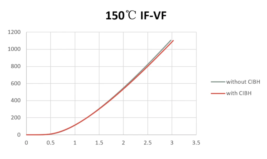
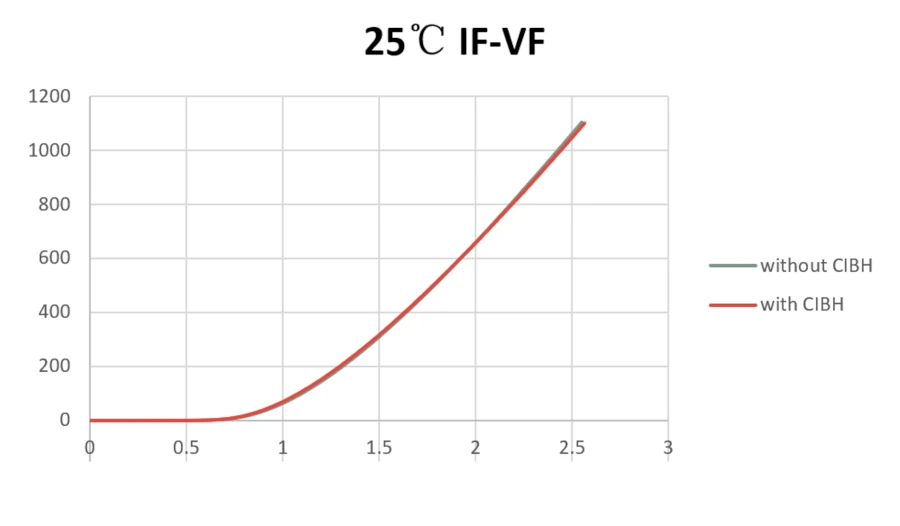
Fig. 3. Direct voltage drops at room temperature and 150 °C.
Figure 4 shows the switching and recovery waveforms of the device shown in Figure 2. The devices were switched with a bias voltage of 800 V, 4600 A/µs, 1200 A, and 95 nH, with a gate resistance of 10 Ω at room temperature. Both devices with and without CIBH exhibit smooth recovery.
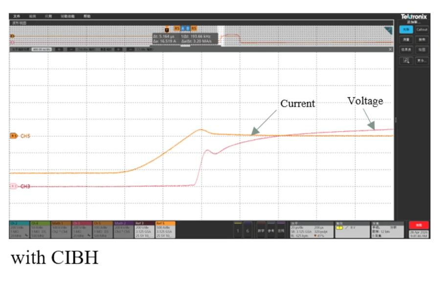

Fig. 4. Switching waveform with a gate resistance of 10 Ω, with and without CIBH, at 25 °C and 1200 A.
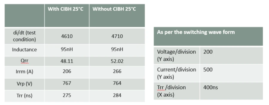
Table 1. Switching losses at room temperature with a gate resistance of 10 Ω.
As the gate resistance decreases to 6.8 Ω, losses increase, as shown in Table 2, and the di/dt rises to 7200 A/µs. During reverse recovery, the reference diode exhibits voltage oscillations, as seen in Figure 5. As the gate resistance decreases, the di/dt switching speed increases. Since there are fewer holes in the base region, the resulting oscillations are clearly visible at the peak voltages (Vrp). The use of a boron-doped CIBH on the cathode side improves smoothness, as the buried p-doped areas inject holes into the base region. Furthermore, Irrm decreases, and the voltage overshoot is reduced.
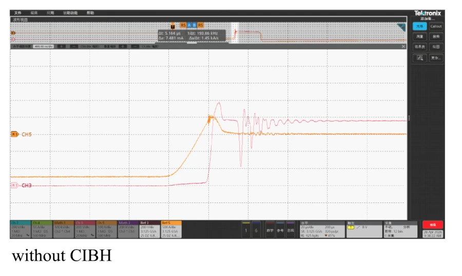
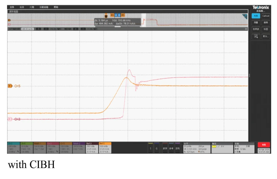
Fig. 5. Switching waveform with a gate resistance of 6.8 Ω, with and without CIBH, at 25 °C.
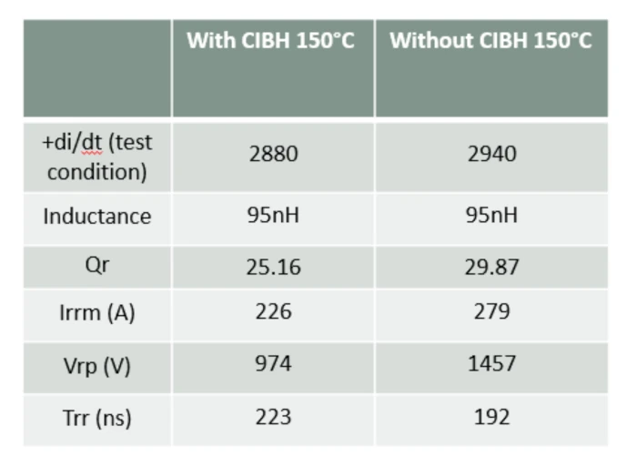
Table 2. Switching loss at room temperature with a gate resistance of 6.8 Ω at 1200 A.
During reverse recovery, an electric field builds up on the cathode side of the diode, between the NN+ junctions. This field is reduced by injecting holes into the CIBH diode. This process leads to smoother operation, as the reverse recovery time (trr) increases from 217 ns to 240 ns, the voltage surge is kept below the diode's breakdown voltage, and robustness is improved.
To verify low-current switching behavior, the devices were switched off with an initial forward current of 20 A and 100 A in a 1000 A module, keeping the gate resistance constant at 6.8 Ω and the module inductance at 95 nH. Since low-current test conditions allow for a better understanding of the switching results, the switching diagrams at 20 A and 150 °C are shown in Figure 6. The waveform clearly demonstrates that, without buried P-layers, the devices exhibit jerky behavior, and Table 3 clearly shows that the voltage overshoot (Vpk) is much higher than that of the buried P-layer. Increasing the boron concentration in the buried layer helps to further reduce oscillations; however, it increases the forward voltage (Vf) and leakage current. A suitable balance must be found between acceptable fast switching behavior and completely smooth switching behavior, taking static losses into account.
The improved and smoother recovery allows the diode to operate at higher di/dt values and current densities without failure. To verify the RRSOA capability of a module, the devices were switched at 2500 A (2.5 times the rated current) and a bias voltage of 800 V with a gate resistance of 6.8 Ω. All module samples passed the same test at room temperature and at 150 °C.


Fig. 6. Switching waveform with a gate resistance of 6.8 Ω, with and without CIBH, at 25 °C and 20 A.
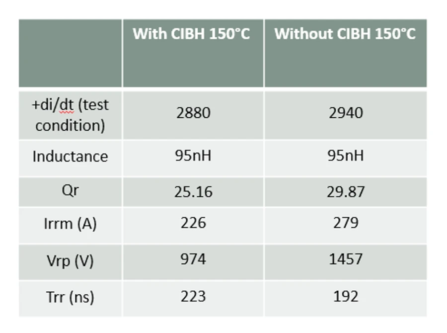
Table 3. Switching losses at room temperature with a gate resistance of 6.8 Ω at 20 A.
Reliability:
VLD termination is used to achieve the highest possible breakdown voltage. When the device is in avalanche mode, the VLD breakdown voltage is completely depleted to the surface; therefore, SIPOS passivation is used to obtain a stable breakdown voltage. SIPOS is deposited directly onto the silicon surface due to its limited conductivity. Any unwanted charges, such as ionic contamination, interface charges, or trapped charges, that might alter the electric field distribution are compensated for by mobile carriers within the SIPOS. The LPCVD machine deposits 0.2 µm of SIPOS with SIN passivation. The conductivity of the SIPOS is carefully adjusted by the oxygen content during deposition.
Prior to official production launch, the devices underwent comprehensive qualification testing. The most important reliability tests for chip electrical stability are the High Temperature Reverse Bias Test (HTRB) and the Humidity Test. The HTRB test verifies the samples' ability to withstand reverse bias while subjected to the maximum ambient temperature for which the components are rated. The HTRB test was conducted at 80% of the rated voltage at 150°C. Breakdown voltage and leakage current were measured before the test began. 156 1400V chips were mounted in the C6 package. The test was conducted for up to 1000 hours, with readings taken every 8 hours. The pre- and post-test measurements showed no increase in leakage current.
The humidity test verifies the ability of the package and chip to resist moisture penetration. The sample is placed in an ambient chamber. The relative humidity is then increased to 85% and the temperature raised to 85°C. The device characteristics are measured before the test begins. The devices are measured again after a 3-hour cooling period. The pre- and post-test measurements show no increase in leakage current.
Author: By JV Subhas Chandra Bose, Hua Shen, Fu Yong, Rebecca Li and Bruce Chen, StarPower Europe AG
Conclusion
Simulation analysis and practical results demonstrate that, by using a VLD structure and an optimized dosage of the buried boron layer, a breakdown voltage of 1550 V can be achieved with an N-thickness of 140 µm. Controlled hole injection on the backface has been shown in practice to provide a smooth recovery diode compared to a traditional diode without a buried P-layer. Reliability results confirm that using SIPOS to passivate a planar PN junction leads to stable reverse voltage characteristics.
REFERENCES
[1] Katsumi Nakamura, Fumihito Masuoka, Akito Nishii, Koji Sadamatsu, Soichi Kitajima and Kazunari Hatade, “Advanced RFC Technology with New Cathode Structure of Field Limiting Rings for High Voltage Planar Diode”, Proc. ISPSD'10, pp. 133-136, 2010
[2] J. Lutz and M. Domeij, «Dynamic avalanche and reliability of high voltage diodes», Microelectronics Reliability, vol. 43, pp. 529-536, 2003
[3] Min Chen, Josef Lutz, Martin Domeij, Hans Peter Felsl, Hans-Joachim Schiulze, “A Novel Diode Structure with Controlled Injection of Backside Holes”, Proceedings of ISPSD'06, pp. 45-48, 2006
[4] K. Nakamura, H. Iwanaga, H. Okabe, S. Saito and K. Hatade, «Evaluation of oscillatory phenomena in the reverse operation of high voltage diodes», Proceedings of ISPSD'09, pp. 156-159, 2009
[5] HP Felsl, M. Pfaffenlehner, H. Schulze, J. Biermann, Th. Gutt, H.-J. Schulze, M. Chen and J. Luts, «The CIBH diode: a major improvement in the robustness and smoothness of high voltage diodes», Proceedings of ISPSD'08, pp. 173-176, 2008
[6] A. Kopta and M. Rahimo, «The field charge extraction (FCE) diode: a novel technology for high voltage diodes with soft recovery», Proceedings of ISPSD'05, pp. 83-86, 2005
[7] M. Rahimo, A. Kopta and S. Linder, “New IGBT technology with improved planar structure and a nominal voltage of up to 6.5 kV to reduce losses and increase SOA capacity”, Proceedings of ISPSD'06, pp. 33-36, 2006
[8] K. Satoh, K. Morishita, Y. Yamaguchi, N. Hirano, H. Iwamoto and A. Kawakami, «A high-voltage diode with a novel structure that stands out for its oscillation-free operation during the recovery process», Proceedings of ISPSD'2000, pp. 249-252, 2000
[9] K. Nakamura, D. Oya, S. Saito, H. Okabe and K. Hatade, «Impact of the LPT(II) concept with thin wafer processing technology on the vertical structure of IGBTs», Proceedings of ISPSD'09, pp. 295-298, 2009
[10] J. Lutz, R. Baburske, M. Chen, M. Domeij, HP Felsl and H.-J. Schulze, "The nn+ junction as a key to improving the robustness and smooth recovery of power diodes", IEEE Trans. Electron Devices, vol. 56, no. 11, pp. 2825-2832, 2009
[11] Y. Tomomatsu, E. Suekawa, T. Enjyoji, M. Takeda, H. Kondoh, H. Hagino and T. Yamada, «Analysis and improvement of immunity to destruction during reverse recovery of high voltage planar diodes under high dIrr/dt conditions», Proceedings of ISPSD'96, pp. 353-356, 1996
[12] JG Bauer, T. Duetemeyer, E. Falck, C. Schaeffer, G. Schmidt and H. Schulze, «Investigations on the 6.5 kV trench IGBT and the matched EmCon diode», Proceedings of ISPSD'07, pp. 5-8, 2007
[13] K. Nakamura, K. Sadamatsu, D. Oya, H. Shigeoka and K. Hatade, “Wide cell pitch LPT(II) CSTBTTM(III) technology with nominal voltage up to 6500 V for low losses”, Proceedings of ISPSD'10, in press, 2010
[14] H. Egawa, "Avalanche characteristics and failure mechanism of high-voltage diodes", IEEE Transactions on Electron Devices, vol. 13, no. 11, November 1966
[15] DESSISISE User Manual, SYNOPSYS INC.