The basic principle:
State machines are often used to solve certain types of control-oriented problems, in which the control flow can be depicted as a movement through a set of different states. There are several different definitions and practical descriptions of a state machine; at a theoretical level, it is like an automaton that responds to a specific stimulus by changing its state. To give a specific, common expression, it can be considered, for example, as an automaton that reacts to the input string by moving through a set of states. If the desired state is reached, the input string becomes equivalent to the common expression.
Within control software, it is common to take the finite and deterministic nature of the state machine as the basis of its computational model. This fundamentally means that the number of possible states or combinations of states is finite, and that the state machine can only have one state at any given time. We will see later that the one-state-at-a-time rule can be relaxed, but the relevant aspect is that the state of the flow is a deterministic property.





- Details
- Category: Design
Designing a state machine to solve a problem
 This article will review how to design a state machine starting from a general problem description. As a starting point, we will use a classic example taken from a hardware design textbook. As we will see, there is usually more than one way to design a state machine to solve a specific problem.
If the implementation of state machines in software is new to you, these are the most important concepts:
States: A state can be considered a shorthand description of the system's current state. As a simple example, consider a peripheral device that can have three alternative operating modes at the highest level: on, off, or standby.
Events: An event is an input message to the state machine. The event can cause the state machine to change state. Pressing the On button on a television in standby mode is a type of event that, with a bit of luck, will bring the television back to life, or to the on state.
Transitions: A transition is a directed path from one state to another. A transition is usually designated with an event name, indicating that the transition will occur if the specified event happens while the state machine is in the transition's starting state. The end result is that the state machine changes state to the state targeted by the transition. To complicate matters—or rather, to increase the expressive power of state machine notation—a transition can be 'protected' by watchdog conditions that must be met for the transition to take place.
Actions – An action is an activity to be performed by the state machine at a specific point in time. Generally, an action performs some task in the environment, such as reading from or writing to an I/O device. Actions can be associated with transitions, or they can be specified as input and output actions in specific states.
These concepts are fundamental to the formal approach to state machine design, which we will find as a subset of the UML modeling language.
States: A state can be considered a shorthand description of the system's current state. As a simple example, consider a peripheral device that can have three alternative operating modes at the highest level: on, off, or standby.
Events: An event is an input message to the state machine. The event can cause the state machine to change state. Pressing the On button on a television in standby mode is a type of event that, with a bit of luck, will bring the television back to life, or to the on state.
Transitions: A transition is a directed path from one state to another. A transition is usually designated with an event name, indicating that the transition will occur if the specified event happens while the state machine is in the transition's starting state. The end result is that the state machine changes state to the state targeted by the transition. To complicate matters—or rather, to increase the expressive power of state machine notation—a transition can be 'protected' by watchdog conditions that must be met for the transition to take place.
Actions – An action is an activity to be performed by the state machine at a specific point in time. Generally, an action performs some task in the environment, such as reading from or writing to an I/O device. Actions can be associated with transitions, or they can be specified as input and output actions in specific states.
These concepts are fundamental to the formal approach to state machine design, which we will find as a subset of the UML modeling language.
Beyond the basics,
let's look at a basic example from a textbook: a state-oriented problem. Let's try to find a suitable implementation on a state machine. In this case, there are actually two different solutions, each with its own advantages and disadvantages, and the choice depends on evaluating their pros and cons.
 The problem: “A busy main road intersects with a lightly trafficked local road. Detectors are placed along the local road to trigger a C signal when a vehicle is waiting to cross the main road. The traffic signal controller should operate as follows: As long as no vehicle is detected on the local road, the traffic signals should remain green in the direction of the main road. If a vehicle is detected on the local road, the traffic signals on the main road should change from yellow to red, allowing the traffic signals on the local road to turn green. The traffic signals on the local road remain green whenever a vehicle is detected on the local road and never for a set interval to allow traffic to flow on the main road. If these conditions are met, the traffic signals on the local road will change from green to yellow and then to red, allowing the traffic signals on the main road to return to green. Even if vehicles are waiting to cross the main road, it should remain green for a set interval.” 1
This exercise focuses on a hardware perspective, but with a little artistic license, it can be adapted for a software environment. Note that the example uses the convention that yellow light always appears on its own (other conventions are used in some parts of the world). But this doesn't actually affect the difficulty of the problem; it simply makes it easier to track the possible color combinations.
The simple approach to state machine design can be described as follows:
1. Identify events and actions
2. Identify states
3. Group by hierarchies
4. Group by concurrency
5. Add transitions
6. Add synchronizations.
This is not a prescriptive recipe, but rather an approach that will generally be helpful in structuring a solution, regardless of the tools and implementation methods chosen.
Let's delve deeper.
Let's begin by examining the problem description, looking for possible events and actions. What constitutes an event in the context of a state machine? Simply put, an event is a trigger that can potentially cause the state machine to change state and perform some action. In the case of semaphores, we can find a series of potential events:
The arrival of traffic on the local road is an event that has implications for the operation of the traffic signal.
There are a few time intervals related to this description:
- The minimum time the main road signal remains green. This can also be used as a fixed time for the local road signal to remain green when
there is traffic.
- The delay when switching to and from the yellow signal for both roads.
There are a few time intervals related to this description:
- The minimum time the main road signal remains green. This can also be used as a fixed time for the local road signal to remain green when
there is traffic.
- The delay when switching to and from the yellow signal for both roads.
Delay intervals are not events in themselves; rather, the end of an interval can be considered an event. In practice, this leaves us with two events: one event for the long interval during the green light period on both roads, and another event for the short, uniform delay during the transition through the light sequence between red and green and vice versa.
This leaves us with three events, which we can call LocalRoadTrafficEvent, LongEvent, and ShortEvent.
 So, what constitutes an action in this problem? Changing the color of the traffic lights is a typical action. The only question is whether changing the light on both roads constitutes one or two actions. The answer is that it's actually a matter of convention. We can consider it as two separate actions, each handling one of the roads, or we can view it as a single action. I choose to consider it as two separate actions, for reasons that will become clear later.
I choose to call the actions ConfigureLocalRoadLight() and ConfigureMainRoadLight(); each action takes a color parameter that indicates the desired color.
The idea here is that the events we've chosen will trigger changes in certain situations where the traffic light colors will be displayed.
We also need a way to track time intervals, so we're introducing a special action called a timer action. Its purpose is to start a timer counter for a specified interval and track an event that will be triggered when the timer reaches its end. For simplicity, we'll call this timer action `ActionTemp()`.
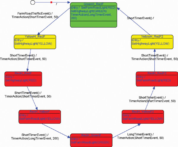
To better understand the control logic of the traffic light system, we need to know the possible states and transitions between them. The first solution will use these observations:
At any given time, the traffic lights will display one of the following color combinations: {GREEN, RED}, {YELLOW, RED}, {RED, RED}, {RED, YELLOW}, {RED, GREEN}, {RED, YELLOW}. Based on the operating rules of a traffic light, it is clear that other combinations should not be permitted to avoid introducing risks to traffic crossing the intersection of both roads simultaneously. The first color in each pair is the traffic light for the main road.
There is a fixed sequence in which the color combinations indicated above will be displayed: {GREEN, RED}, {YELLOW, RED}, {RED, RED}, {RED, YELLOW}, {RED, GREEN}, {RED, YELLOW}, {RED, RED}, {YELLOW, RED}, and then back to the first combination to start again.
It doesn't take much to see each stage of the sequence as a possible state, since it clearly includes the state of the system at a given moment. The transitions between states would then be triggered by the different time intervals for each color change. Assuming the sequence begins with a green light for the main road, then the entire sequence is triggered by a LocalRoadTrafficEvent.
The observant reader will have noticed that there are some duplicates in the sequence of color combinations above. For example, the combination “both traffic lights red” appears twice. Should we treat these as one state or two? I have chosen to treat all positions in the sequence as separate states. This decision implies that the transitions between states should be as simple as possible.
We already have the foundation in the form of a set of events, some actions, and a set of candidate states.
Figure 2 shows the design in UML notation. The proposed states are drawn in a circular shape with transitions named after the corresponding events. The states also have input actions to change the traffic light color. As we can see, only the start state needs to configure both traffic lights to ensure a correct start to the sequence; for the other states, only one light needs to be changed from the previous state. This explains the use of two different action functions. The start state is indicated by the transition between the initial state and the current state, denoted by a small circle in the upper left corner.
 UML semantics uses the initial state and the transition from it to point to the desired starting state, meaning we can express system initialization directly in the diagram. The transition lacks any event and is implicit in the startup.
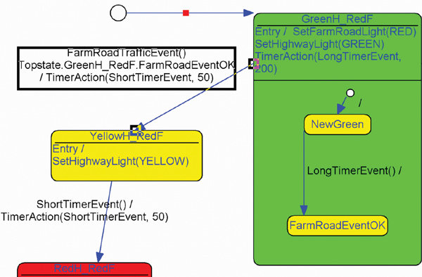
From a state machine perspective, this design is almost complete but lacks the handling of a minimum green interval for the main road. We can solve this in several ways, but the following solution seems quite simple.
Introduce a small amount of hierarchy into the model by creating a state machine within the state MainGreen_LocalRed. This state machine consists of two states plus the initial pseudo-state. Whenever the surrounding state is entered, the NewGreen state will also be activated.
When a long time interval, which began upon entering MainGreen_LocalRed, expires, we let the small state machine change state to LocalRoadEventOK. We now know that the minimum green interval for the green light on the main road has passed and that it should now be correct (OK) to 'turn green' on the local road if there is traffic there.
The final piece needed to maintain the minimum green interval on the main road is a 'protection' in the transition out of the GreenMain_RedLocal state. This transition should only be overridden if the LocalRoadEventOK state is triggered. This can be expressed as a positive state condition or positive synchronization in the transition. The resulting changes can be seen in Figure 3.
This solution is not perfect because it doesn't account for the fact that traffic arriving on the local road during the minimum green interval on the main road remains stopped until another car arrives once the interval expires. To address this, we need to log any LocalRoadTrafficEvent that occurs during the green interval so that we can take appropriate action when the interval expires. We will not study a complete solution to the problem here, but if you attempt to design a solution, the following points indicate a possible path forward:
Introduce an internal alert variable in the state machine that is reset to zero with each entry of the green state on the main road.
Introduce an 'internal reaction' in the green state of the main road that sees the alert if a LocalRoadTrafficEvent is received, perhaps with NewGreen as the protection state.
An 'entry reaction' in the LocalRoadEventOK state that sends a signal if the alert is triggered upon entering the state (a signal is a special event that the state machine itself can send).
A transition to Yellow that triggers the signal and starts a short timing interval.
There are other ways to address this problem, but they require more complex UML syntax, which is too extensive to cover here.
Software state machines differ from their hardware counterparts in that the software state machine must detect and react to events in the hardware environment. This means that the computational model of software state machines is based on a detect-event-react-to-event cycle composed of discrete steps, whereas a hardware state machine can react 'simultaneously' to a changed signal on a given pin. (Although the actual variation of the gates is, of course, discrete activity at the bit level.) For example, a set of hardware signals can be combined at a gate to produce an event when a certain combination of signals is present on the input side. In a software environment, you either have to let the interrupt and device drivers perform the combination or let the state machine do it. (Unless you control the hardware design.)
A Different Approach
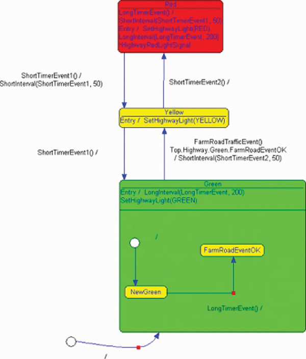
As emphasized at the beginning, there is at least one completely different way to solve the same problem, which involves modeling the state machines as two parallel regions within the same high-level state machine. This has the advantage that the complete solution can be viewed as a system made up of separate and semi-independent components. Space does not allow for a more extensive comment, but it can be consulted online at www.iar.com/p236597/p236597_eng.php
.
The exact solution chosen is not actually important, but in general, it is good to keep things as simple as possible. Using a graphical design tool like IAR visualSTATE for state machine design is a practical way to raise the level of abstraction, as a good tool provides support for aspects such as code generation, testing and simulation, and verifying the model's capabilities.
Author: Anders Holmberg, IAR Systems




Print Magazine

Annual subscription price:
You will receive all 10 editions that are published each year.
social networks
Popular News Electronics

Spanish electronics magazine. Printed for over 25 years.
Spain - Madrid - All rights reserved © Convertronic Professional Spanish Electronics Magazine.