This design transmits pulses of infrared light into space and reads the reflected light data received by the light sensor. A moving object (such as a hand) in this space reflects the infrared light onto the light sensors. The design then detects this light and generates a response based on the object's position.
The typical gesture sensing range is up to 20 cm and the sampling rate is up to 512 samples per second, allowing the response time and noise rejection to be adjusted to suit the specific requirements of the application.
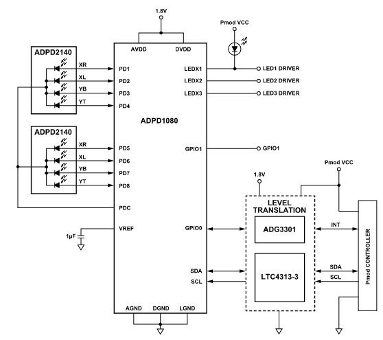
Figure 1. Circuit block diagram
The system performs three basic functions:
> Detect the beginning and end of a gesture.
> Track hand movement during the gesture.
> Identify the gesture based on hand movement.
Infrared light angle sensor
The core of the circuit is the ADPD2140 infrared angle sensor. This device performs two-axis, single-point measurements of infrared light incidence angles. Multiple devices can be used for distance triangulation. The ADPD2140 is divided into four photodiode channels with a common cathode terminal.
The ADPD2140 includes a built-in optical filter with a sharp cutoff of visible light, eliminating the need for external lenses and preserving the sensor's dynamic range when placed under sunlight or indoor lighting. When selecting an infrared light source for this design, it is important to choose one that operates at a wavelength above 800 nm so that the light can pass through the ADPD2140's internal optical filter. The light source should also be positioned at a distance from the sensor such that the reflected light falls within the +/-35° field of view. In this reference design, an 850 nm infrared emitter serves as the light source and is positioned 6 mm from the first ADPD2140 and 19 mm from the second, as shown in Figure 2.

Figure 2. Placement of the ADPD2140 + LED
Photometric front
In the circuit, the photometric front panel is the ADPD1080. It is a highly integrated device that includes LED drivers, transimpedance amplifiers, integrators, an analog-to-digital converter (ADC), digital signal processing, and an I2C interface.
The ADPD1080 is responsible for pulsing the infrared LED, sensing the response of the ADPD2140, converting the analog photocurrents to digital codes, and sending the data to an external microcontroller via I2C. With eight high-performance parallel photodiode input channels and a compact design, the ADPD1080 can be used with the ADPD2140 to create a discrete, low-cost solution for light angle detection using synchronized LED pulses.
The circuit uses two ADPD2140 infrared light sensors connected to the ADPD1080, facilitating gesture and distance detection. Figure 3 shows a simplified block diagram of a typical measurement channel.
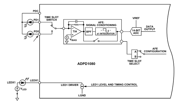
Figure 3. Typical measurement channel
The ADPD1080 has three LED drivers (LEDX1, LEDX2 and LEDX3) that can be used to power external LEDs.
During a sampling period, the LED is pulsed and the transimpedance amplifier stages convert the photodiode currents into voltages. These output voltages are then integrated within a window programmed for the time interval.
The LED then turns off and is integrated in the opposite polarity for the same period of time, after which the ADC digitizes the integrator's output. This synchronous sampling sequence rejects ambient light, as the measurement relies solely on the light reflected by the LED.
The ADPD1080's measurement path is highly configurable; transimpedance gain, integration time compensation, averaging, and other parameters can be adjusted to suit the end application.
Power regulation and level shift
The LT1761 is a low-noise, low-dropout micropower regulator with a wide input voltage range of 1.8 V to 20 V and a maximum output current of 100 mA. The fixed 1.8 V variant requires input, output, and noise-reduction capacitors.
Because the ADPD1080 uses 1.8 V logic for its digital lines, a level-shifting function is included in this design to ensure compatibility with driver boards that operate with 3.3 V logic. For the ADPD1080's I2C bus, the data and clock lines are routed through an LTC4313-3, a hot-swappable, two-wire bidirectional bus buffer that also supports level shifting to 1.8 V. Figure 4 illustrates the connection configuration of the ADPD1080's I2C bus data and clock lines to the LTC4313-3.

Figure 4. Connection diagram of the LTC4313-3
Similarly, for the GPIO0 pin of the ADPD1080, the data line passes through a single-channel ADG3301 level shifter.
Reference
"CN-0569 Circuit Note: Infrared Gesture Recognition Module", Analog Devices, Inc., May 2022.
Translation and adaptation by Diego de Azcuénaga, Electronics Engineer. Facebook: diego.deazcuenaga