


The aim of this article is to review the practical aspects of operational amplifiers, explain some of the basic parameters in their technical specifications, and show some potential applications of which they are an important part.
The operational amplifier: a modest element
Operational amplifiers (OPs) first came into being in the 1940s, when the concept of a high-gain, DC-coupled voltage amplifier employed thermionic vacuum tubes. The first OPs were quickly adopted in a variety of applications, from radar to analog computers, and their usefulness continues to grow. Today, OPs are the foundation of almost every electronic device, from fitness watches to industrial robots, autonomous vehicles, and communication satellites.
One of the most popular op-amps is the 741, which is still manufactured today. Although not the first monolithic semiconductor integrated circuit operational amplifier (that title belongs to the Fairchild 702), the Fairchild µA741 quickly became the benchmark op-amp for virtually any design. Released in 1968, it is still in production and is sold by numerous suppliers in pin-compatible packages, such as STMicroelectronics and Texas Instruments.

Image 1: Internal schematic of the generic, multi-stage UA741CD op-amp from STMicroelectronics (source: ST).
Typically, an operational amplifier (op-amp) has an unbalanced output and inverting and non-inverting differential inputs. When used as an open-loop amplifier, its high gain creates an output thousands of times greater than the potential difference between the inputs. Op-amps are frequently used in closed-loop configurations (Figure 2) with negative feedback to limit and control the gain according to the application's requirements. The output voltage of the operational amplifier is limited by the supply voltage, regardless of the gain specifications.
 Image 2: Non-inverting, closed-loop op-amp with negative feedback through R2 (source: Mouser).
The gain of the non-inverting amplifier can be seen in image 2; the output voltage (Vout) is determined by the set of resistors R1 and R2.
Operational amplifiers can be configured as differential amplifiers, voltage followers, differentiators, or integrators. They are ideal for a variety of applications, some of the most common being active filters, level converters, buffering, signal conditioning, small-signal amplification (AC/DC), and function generators. In short, they are a perfect component for virtually any device.
To understand how an operational amplifier works, it is helpful to understand that an ideal device would have these characteristics:
- Infinite differential voltage gain: the output voltage depends only on the input voltage and the feedback circuit.
- Infinite input resistance, so there will be no current at any input.
- The output resistance is zero, and therefore the load does not affect the amplifier's performance.
- Infinite bandwidth, so it adapts to DC and any frequency without changes in phase or gain.
- Zero output when the differential input is zero.
If you'd like to see a helpful infographic on the basics of op-amps and some popular circuit configurations, you can download it from Mouser here: https://emea.info.mouser.com/opamp-reference?pid=Mouser&cid=TW
Operational amplifiers in practice
To understand the operating theory of an AO, it is helpful to use an ideal device, but in reality, all AOs have certain attributes that engineers must understand well.
In this section of the article, we'll explain some of the most important parameters found in an AO's technical specifications. Some of these criteria may directly influence the device you choose, depending on the type of application.
Input offset voltage: In an ideal op-amp, the output should be zero when the differential input is also zero. However, due to slight variations in device manufacturing, not all transistor gates are identical. The input offset voltage is the voltage that must be applied to the differential inputs to generate a zero-volt output (Vio). Typical Vio values can vary widely, from a few microvolts to hundreds of millivolts. Vio is an important factor when measuring very low input voltages, as this will result in an inaccurate output voltage reading.
Input bias current: This is the unwanted current that reaches the differential inputs. It is usually caused by leakage currents, and its value can vary depending on the processing technology, although it can also be generated when bias components are present near the inputs. Even when an input bias current (Iib) is very small (typically pA or nA), it can cause a significant drop in the voltage of input circuits with high impedances, thus affecting the output.
Gain-bandwidth Product (GBP): This factor illustrates the performance of an op-amp over a range of frequencies. Typically, the gain gradually decreases as the frequency increases. It indicates the frequency at which the gain drops by 20 dB.
Rail-to-rail inputs: an op-amp with rail-to-rail inputs can accommodate input voltages between +Vcc and -Vcc.
Rail-to-rail outputs: as in the previous element, the output voltage of an op-amp can go from +Vcc to -Vcc.
Switching speed: The switching speed determines how quickly the op-amp's output can change in response to the input signal. In high-frequency applications, this factor is crucial because if the output cannot keep pace with the input's rate of change, the signal will be distorted. It is measured in mV/s, and the output voltage can range from 10% to 90% of the peak value (Figure 3).
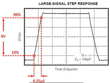 Image 3: Measurement of the rate of change of an operational amplifier considering changes in the input signal (source: TI).
Input capacitance: The input capacitance of an op-amp can influence its performance as the frequency of the input signal increases. The importance of this factor will depend on the application. It is not very relevant when measuring battery voltage, but with active filter or ultrasonic signals, it is something that must be taken into account.
Noise level: As with many components, operational amplifiers have various noise sources that can introduce noise into the output signal when there is no input, such as thermal noise or 1/f noise. It is advisable to choose an op-amp with a low noise level for high-gain, high-bandwidth applications.
Zero deviation: The impact of factors such as input offset voltage, described above, depends on temperature and time. In a zero-deviation op-amp, an input switching or cutting technique is used to eliminate these influences.
Current consumption: Energy consumption is becoming a priority in many applications, not only to optimize energy efficiency but also to extend battery life, especially with IoT/IIdC sensors. Operational amplifiers (op-amps) have much lower power specifications than other integrated circuits (ICs), such as microcontrollers. However, there are op-amps with particularly low power levels and operating currents as low as 900 nA per input that are an ideal choice for battery-powered applications.
Examples of operational amplifiers
Semiconductor suppliers typically optimize their operational amplifier range by organizing them into different categories based on device specifications. For example, ST divides them into low-power, low-input-offset-voltage, high-voltage, precision, rail-to-rail, and high-speed products. Analog Devices uses a similar method and identifies products for specific applications.
The ST TSZ121 series is an example of a precision op-amp, featuring low input offset and zero drift. It is available in various packages (single, dual, or quad) and is a rail-to-rail input/output device. It can operate with an input voltage between 1.8 and 5.5 V DC, has a maximum low-power profile of 40 µA (at 5 V), and a typical offset voltage of 5 µV (at 25 °C). This series is ideal for portable and battery-powered applications, signal conditioning circuits, and medical instrumentation.
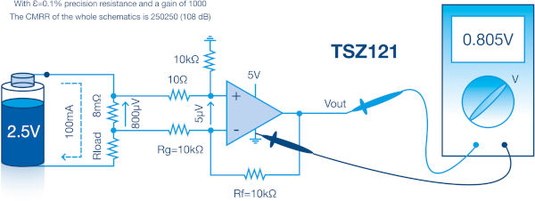 Image 4 shows the use of the TSZ121 in the current measurement circuit of a battery-powered device.
Image 4: Example of using the ST TSZ121 precision op-amp to measure current in a portable device: it is important to select an op-amp with a low input offset voltage level (source: ST).
An 8 mΩ precision shunt resistor is placed in series with the battery load. A 100 mA current flows through this resistor, generating an 800 µV voltage, which is applied to the differential inputs via two 10 Ω resistors. The op-amp configuration has a gain of 1000, so there should be 0.8 V at the output. However, in practice, with an input offset voltage of 5 µV, the actual output voltage measured is 0.805 V. This example illustrates the importance of the input offset voltage in a measurement. For instance, if we had selected an op-amp with an input offset voltage of 200 µV, the measurement error would have been much larger.
A low-side prototyping board, the STEVAL-ISQ014V1, and includes a 30 mΩ shunt resistor. Additionally, to help engineers develop and emulate operational amplifier circuits, ST's eDesignSuite offers a practical and fast method for selecting a design and creating prototypes (see Figure 5).
 Image 5: A current measurement design in ST's eDesignSuite with an AO TSZ121 (source: ST).
Op-amps are also frequently used in active filter circuits. Figure 6 shows the design of an audio frequency bandpass filter using the Analog Design Filter Wizard.
 Image 6: Design of a bandpass filter with the Analog Design Filter Wizard (source: Analog Devices).
The filter parameters are a center frequency of 800 Hz and a passband of 300 Hz at 3 dB. We can quickly adjust the filter parameters to achieve the desired passband. The next step is to select the components (see Figure 7). We can accept the wizard's suggestions or manually choose our desired components from the Analog Devices AO catalog.
 Image 7: Schematic of the bandpass filter circuit with a low power ADA4062 op-amp selected for the first stage (source: Analog Devices).
The Analog Devices ADA4062 has a typical switching rate of 3.3 V/µs, a low input bias current (50 pA), and an input offset voltage of 500 µV. It can operate on ±5 to ±15 V rails and its typical power consumption is 165 µA.
Why not add an AO to your next design?
Operational amplifiers play an important role in battery-powered applications. Thanks to their ultra-low current specifications, they can continuously measure or condition signals without significantly impacting battery life. They are flexible devices that can be integrated into any design.
Author: Mark Patrick, Mouser Electronics