

Introduction
The increasing demand for portable electronic devices has driven the need for efficient, portable power management systems. Portable chargers have become indispensable accessories, providing a reliable backup power source for smartphones, tablets, and other USB-powered devices. Using evaluation demo boards, we first created a modular portable battery charger solution as a proof of concept. This prototype was assembled by stacking demo boards and subsequently evolved into a single-board solution with improved performance and other enhancements. This solution accepts multiple input sources, such as batteries, solar power, or DC adapters, and intelligently manages the power flow to charge the battery and simultaneously power the load.
The objective of this article is to explore the intelligent power path management capabilities of Analog Devices integrated circuits in a compact design without compromising performance. It describes the design considerations, concept, and performance evaluation of the single-board solution and highlights its improvements over the multi-board proof of concept.
Block Design:
In this layout design, a compact and optimized architecture has been developed to support two wide-range input voltages, specifically from a solar panel and an AC-to-DC adapter. The power input is intelligently managed using the LTC4416 power path controller in conjunction with the LTC4162 power path buck charger . This configuration enables the efficient charging of various lithium-ion batteries with configurations up to 4S1P.
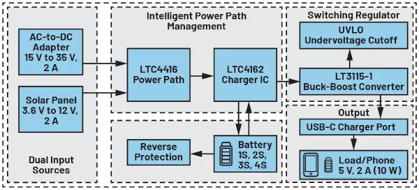
Figure 1. Single-plate design block.
As illustrated in Figure 1, the system features a buck-boost switching regulator, LTC3115-1, which dynamically regulates the output voltage to the load and ensures a constant maximum output of 5 V and 2 A, while the LTC4162 monitors the battery charge level.
Component Selection and Layout Design:
The three main components optimize system performance based on the design block configuration. These components were selected to improve system efficiency, minimize power loss, reduce the printed circuit board footprint, and lower the overall cost. Their schematic design is shown in Figure 2.
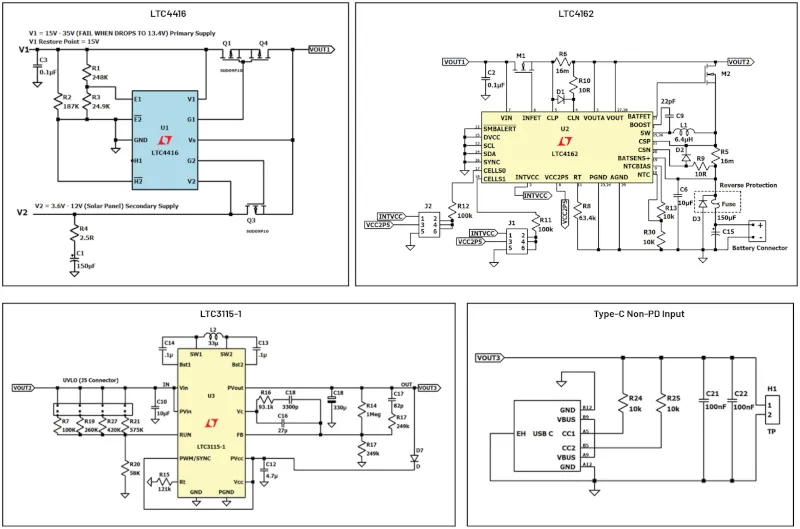
Figure 2. Schematic single-plate design.
1. Dual Input Sources with the LTC4416
A simple OR gate configuration, using diodes, can be employed to switch between two input power sources. However, this approach introduces significant power loss due to the inherent forward voltage drop of the diodes, even when using low-dropout Schottky diodes. The LTC4416 creates seamless switching between two sources with a very low forward voltage drop, thus reducing power loss. By controlling external P-channel MOSFETs to emulate ideal diodes, this device significantly reduces conduction losses, thereby improving overall system efficiency and reliability.
The LTC4416 operates in six different modes. Each operating mode depends on the configuration of the input pins E1 and E2, as indicated in the datasheet. In this configuration, the selected mode is: V1 is greater than V2, where E1 is set to Sense and E2 is set to 0. This means that the chip prioritizes power source V1. In this operating mode, the IC is configured to prioritize V1 for a wide input voltage range of 15V to 35V DC, while the secondary voltage source, V2, is a solar panel (3.6V to 15V). When V1 is greater than or equal to 15V, E1 allows V1 to become the primary voltage source and disables V2, since V1 is higher than V2.
When V1 drops to 13.4V, V2 becomes the primary power source, and V1 is disconnected from the output. As long as the solar panel voltage is between 3.6V and 15V, V2 will continue to supply power to the output load until V1 is restored. The reset point of V1 is set to 15 V, as shown in Figure 2.
The fault and restore points of V1 can be modified by changing the values of resistors R1, R2, and R3 in Figure 2. This can be done using the formula shown in the datasheet:


Once V1 is identified, V2 can be selected to ensure the best configuration. If V1 fails or becomes unavailable, the system automatically switches to V2 to maintain power until the restoration point is reached, provided V1 > V2. Since the power output follows the highest voltage source, restoration will not occur if V2 > V1.
2. Intelligent Power Path Management.
In applications such as portable chargers and other devices that require simultaneous battery use and charging, implementing power path charging is an ideal solution. This approach helps optimize battery performance and extend its overall lifespan by efficiently managing power distribution between the system and the battery. The system intelligently manages power input by selecting from three sources: the AC-DC adapter, the solar panel, or the battery. The AC-DC adapter or solar panel is primarily used to charge the battery.
If the AC-DC adapter fails and the solar panel voltage drops below the minimum value, the system automatically switches to the charged backup battery to power the load. The output of the LTC4416 power supply path feeds the LTC4162-L, which supports input voltages up to a maximum of 35 V.
The LTC4162-L supports immediate operation even with a discharged or missing battery and features an integrated maximum power point tracking (MPPT) system to improve the efficiency of solar energy conversion.
Under intense sunlight, the solar panel operates in two regions: low impedance at constant voltage and high impedance at constant current. This behavior ensures that the device's control loop remains stable when operating at a lower impedance (e.g., the higher voltage region). However, because the integrated circuit uses the input voltage to find the MPPT, the solar panel voltage drops due to the higher impedance (e.g., the lower voltage region), causing the control loop to become unstable. In the design, the solar panel input operates at high impedance (
3. Backup Lithium-Ion Battery
The LTC4162 battery charger supports configurations of up to eight series-connected lithium-ion cells (8S) and is available in multiple variants optimized for different battery chemistries: LTC4162-L for lithium-ion, LTC4162-F for lithium iron phosphate (LiFePO4), and LTC4162-S for lead-acid batteries. In this design, we have implemented compatibility with configurations of up to 4S (1S to 4S power supply) of stacked lithium-ion cells, as shown in Table 1.
Table 1. Battery configuration settings
| CELLS1 (J1) | CELLS0 (J2) | Cell count |
| INTVCC | INTVCC | 1 |
| INTVCC | VCC2P5 | 2 |
| INTVCC | GND | 3 |
| VCC2P5 | VCC2P5 | 4 |
This configuration is defined using the CELLS1 and CELLS0 pins, following the assignment guidelines provided in Table 1.
4. Switching Regulator
The output of the LTC4162-L is then regulated by a synchronous buck-boost switching regulator. The LTC3115-1 is a high-efficiency, monolithic, synchronous buck-boost DC-DC converter designed for applications requiring a wide input voltage range and low noise. It operates between 2.7 V and 40 V and can supply up to 2 A of DC current. This switching regulator also features programmable output voltage, smooth transition between buck and boost modes, and robust protection functions, making it suitable for industrial and battery-powered applications.
It was selected for this design because of its excellent efficiency and quiet operation. The converter can supply up to 2 A when the input voltage exceeds 6 V, and 1 A for voltages above 3.6 V, making it highly adaptable to varying power supply conditions. For all battery configurations (1S, 2S, 3S, 4S), an undervoltage lockout (UVLO) was configured through the connector, as shown in Figure 2 (connector J5).
5. USB Type-C Output
The output was configured with a USB Type-C in no power delivery (PD) mode to charge any portable device that requires a regulated 5V output with a current of up to 2A. Table 2 describes the choice of resistor values for different current sources for the USB port.
Table 2. Current supplied by USB Type-C without PD
| Power source | Pull-up resistor value (R24, R25) at 4.75 V to 5 V |
| Up to 1.5 A at 5 V | 22 kΩ ±5 % |
| Up to 3.0 A at 5 V | 10 kΩ ±5 % |
Single-Board Performance:
The board was specifically designed as a 4-layer PCB to ensure stable, noise-free, and efficient operation, as shown in Figure 3. The layout follows a SIG/Power – GND – GND – SIG/Power stacking configuration, and the component placement recommendations provided in the datasheet are used for each component. The board receives power from two inputs, V1 and V2, which are used to charge the battery and power the load. If the main power supply fails, the solar panel takes over during periods of high solar intensity and provides power to the load while simultaneously charging the battery. At night or when solar intensity is low and the solar panel voltage drops, the system automatically detects this and switches to battery power to maintain load operation.
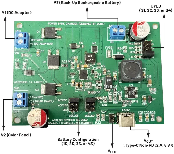
Figure 3. Single-board solution in operation and tested.
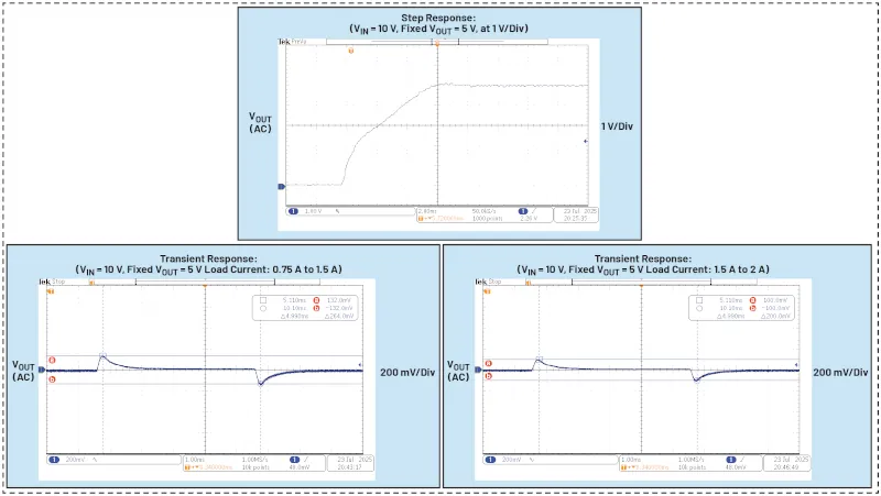
Figure 4. Transient and step response analysis.
Assuming a 1S battery configuration, if the battery voltage drops below 3.3 V, the LTC3115-1 will automatically shut down to protect the battery by activating the UVLO function. This mechanism helps prevent deep discharges, which can damage the battery or reduce its lifespan. The UVLO threshold can be precisely adjusted for each battery configuration by changing the values of resistors R7, R19, R27, and R21. This can be achieved using the UVLO formula in the LTC3115-1 datasheet. This will allow the minimum voltage limit to be set as low as 3.0 V, depending on the application requirements.
To protect the circuit against incorrect battery connections, reverse polarity protection has been implemented using a diode (D3) and a fuse (FUSE1). Furthermore, the input is additionally protected against reverse voltage by the body diodes of MOSFETs Q1, Q4, and Q3, which act as a barrier against unwanted current flow.
The dynamic behavior of the system under varying load conditions is illustrated through its step response and transient response characteristics, as shown in Figure 4, which demonstrates the performance of the control loop and the effectiveness of the applied compensation network across a wide range of operating conditions. Figure 5 illustrates the priority switching behavior of the LTC4416 output as V1 decreases from a higher voltage to 15 V. The device output seamlessly switches to V2 at 8 V, ensuring that the output load ee is unaffected by the voltage change. Meanwhile, the reset point of V1 is set at 16.8 V.
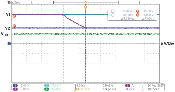
Figure 5. LTC4416 priority switching from V1 (15 V) to V2 (8 V) with a constant output load voltage (fixed VOUT = 5 V; load current = 1 A, R1 = 281 kΩ and R3 = 24.9 kΩ).
Comparison of Stacked Demo Boards with a Single Board
This section provides a comprehensive comparison between the prototype multi-demo board configuration and the newly developed single-board solution. In the prototype, the design used three independent demo boards: the LTC4416 for ideal diode power path control, the LTC4162-L for battery charging and power management, and the CN0509 USB charger board . The CN0509 was particularly noteworthy for its wide input voltage range of 5 V to 100 V and its ability to provide a regulated 5 V output at up to 2 A. It combines the LTC7103 buck converter and the LT8302 isolated flyback converter to provide galvanic isolation between the input and output.
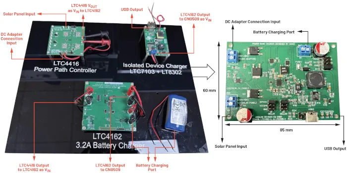
Figure 6. Dimensions of the prototype stacked demonstration board versus those of the single board.
Conversely, the single-board design consolidates these functionalities by replacing the LTC7103 and LT8302 with a single component: the LTC3115-1. The goal of this transition was to improve overall system performance, with increased efficiency, reduced physical size, and a more cost-effective bill of materials. While some features, such as isolated output, were sacrificed, the trade-off resulted in a more streamlined and practical design, well-suited for scalable applications.
Physical Board Size
: Implementing a single-board solution significantly optimizes the overall system design by reducing the bill of materials (BOM) by approximately 30% and its size, as shown in Figure 6.
Furthermore, the compact nature of the single-board solution contributes to a more efficient power system architecture. By integrating multiple functionalities onto a unified platform, the design becomes more space-efficient, enabling smaller form factors without compromising performance. This is especially beneficial in applications where space constraints are critical, such as portable electronic devices.
Efficiency:
One of the most striking improvements of this board is its ability to deliver power with high efficiency. Optimized power delivery reduces energy losses, which, in turn, allows for longer operating times and improved thermal performance. High efficiency is valuable in battery-powered devices, where energy conservation directly translates to longer battery life cycles. By minimizing energy waste and maximizing its utilization, the single-board solution plays a crucial role in improving system performance. Figure 7 shows that the single-board solution achieves a maximum efficiency of 92.94% with an 8 V input and 91% with a 10 V input. In comparison, the prototype stacked demo board only achieved a maximum efficiency of 73.79% with a 10 V input. The low efficiency of the prototype stacked demo board is clearly due to power losses in the wires used to connect the multiple boards, as well as losses in the flyback converter section.
When both input sources fail, the battery automatically powers the load. Using a 2S battery configuration with a nominal voltage of 7.4 V, the single-board solution achieves a maximum efficiency of 94.52%, compared to 77.12% for the prototype stacked demo board. This indicates that the single-board design conserves battery energy more effectively during system operation, as shown in Figure 7. From the optimized single-board solution, a maximum output current of 2 A is achieved from an input voltage of 6 V, whereas in the previous prototype board, a maximum current of 2 A is achieved from 12 V, as shown in Figure 7.
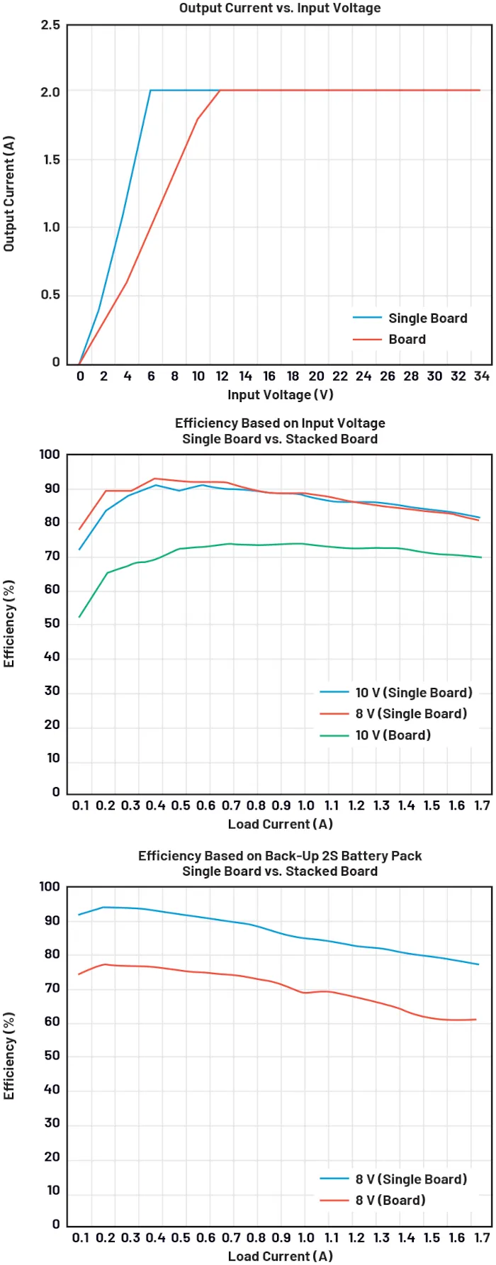
Figure 7. Output current regulation and efficiency (single board vs. prototyped stacked demonstration board).
Conclusion:
A compact, integrated, single-board power bank solution has been developed using ADI components. This refined design features an optimized layout that improves overall efficiency and reduces the physical footprint. The architecture is versatile and adaptable, making it suitable for a wide range of applications involving battery-powered devices. It supports intelligent power path management, which will extend battery life.
This concept can be used in integrated automotive systems to combine photovoltaic input with other power sources and backup batteries in large-scale production. In such configurations, high-power ADI products such as the LTC4020.
Reference:
Diarmuid, Carey. "How to create a prototype portable battery charger without building any specific hardware." Analog Dialogue, February 2023.
About the author

Dr. Uchechukwu Maduagwu works as an Applications Engineer on the central applications team in Dublin. He joined Analog Devices in 2023 and provides design support for the energy management portfolio, serving customers across the broader European market. Dr. Uchechukwu holds several degrees.