

We must also consider radiated or conducted noise from internal and external sources. Electrostatic discharges and lightning surges can disrupt or even destroy systems, and thermal stress, mechanical stress, and component aging can lead to system failures. In this article, we will look at some of these problems and the measures we can apply to our designs to eliminate or at least minimize them. We will also see how some of the features we implement in our microcontrollers can mitigate many of these problems.
Twenty-five years ago, we designed with microcontrollers implemented on 1.0μm or even 0.8μm CMOS technology. Today's devices use significantly more advanced process technology, with linewidths orders of magnitude smaller. The latest microcontrollers in Renesas' RA family are implemented on the latest 40nm and 22nm process geometries.
As the size of transistors in the latest devices gets smaller and the switching frequency of transistors gets faster, noise becomes an increasing concern.

Diagram 1: Signal vs. Noise
Diagram 1 shows a simplified comparison between a 1.0 µm device operating at 8 MHz and a modern device operating at 100 MHz on a 40 nm process. It is clear that the switching time of the 40 nm device is much faster and that the signals we deal with can be faster than the typical noise signal. Noise becomes a greater concern as we move toward smaller process geometries. Renesas has taken several steps forward in our devices, designing them with features that help them operate in such an environment, with carefully designed power circuits, optimized I/O buffers, and specialized protection circuitry, but it remains important to minimize any effects on our designs as much as possible. After all, once noise enters the device, it is much more difficult to remove.
External noise sources are often one of the biggest threats to reliable operation. For example, switching noise from a power supply, noise from sparks in industrial machinery, motors, etc. Other sources include induction noise from relays, transformers, buzzers, fluorescent lamps, etc., as well as static discharges, usually from the user's body, but also from other locations, and, of course, lightning.
Internal noise can come from a wide variety of sources. Current loops on a printed circuit board can be a significant source of radiated noise. If current flows in a closed loop formed by the MCU and its I/O signals, as shown in Diagram 2, this current loop can act as an antenna, and significant noise can be radiated, especially if the current is high.

Diagram 2: Current loops on the PCB
With a poorly designed ground plane, where there's a voltage difference between ground at different points on the PCB, current can flow between these points, acting like an antenna. Poorly designed oscillator circuits can also radiate noise. We always advise users to adhere to the recommended circuit parameters and ground plane. This is especially important because a poorly designed oscillator can project noise onto many parts of the circuit, and a poorly designed oscillator circuit can also fail.
Another key area is the I/O system, especially with multiple high-speed devices on an external bus. A poorly designed I/O system, where overshoots or undershoots occur, can cause devices to exceed their electrical specifications. This can damage devices over time and lead to failures, as well as increased power consumption and noise radiation.
Noise can affect any pin on a microcontroller. However, microcontroller system pins are particularly sensitive to noise, as they often control the device's fundamental operation, and a noise-induced fault could cause the device to malfunction. Therefore, special care must be taken to ensure that the possibility of noise interfering with the normal operation of the system pins is minimized.
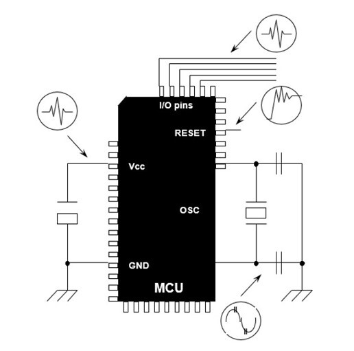
Diagram 3: Microcontroller system pins
The system pins on a typical microcontroller may include the reset pin, power supply pins, oscillator pins, and special mode or function pins. To minimize the possibility of noise affecting these pins, we must take special care, ensuring that the power supply pins have solid voltage levels with the necessary filtering and that the ground plane has no current loops. We must also ensure that the oscillator is placed as close to the chip as possible, that the printed circuit board layout follows the vendor's recommendations, and that the reset pin is protected from fast transient signals.
There are some useful rules we can use in our designs to minimize the effects of noise.
- Protect memory/clock traces from other signals.
- Consider filtering and/or buffering external connections.
- Always use high-frequency Vcc/Vss bypass capacitors near each device.
- Always use Vcc/Vss in parallel and as close together as possible to minimize current loops.
- Use parallel signal/return traces on the printed circuit board, especially for fast signals or traces that carry a lot of current.
- Consider using a multilayer board with dedicated, uninterrupted Vss/Vcc planes.
- Don't use a higher frequency than necessary; this is not only good for minimizing noise but also power consumption.
Let's look at some of these points in more detail.

Diagram 4: Relationship between the microcontroller and the PCB
We should try to keep the area between the feed lines as small as possible to minimize the potential antenna. We should also minimize the current flow to this antenna to keep radiated noise to a minimum.
The system's power supply is often one of the biggest sources of internal noise. We should design an effective power distribution system using bypass capacitors and EMI filters. We should also keep the antenna pattern area between the feed traces on the PCB as small as possible so that the surrounding current loop area (S0, S1, S2) is minimized. The most effective way to do this is to use parallel traces for the Vcc and Vss lines.
A bypass capacitor connected across the feed lines to each integrated circuit will significantly reduce noise, so we should try to keep them as close to each device as possible. Typically, the most effective capacitor values are 0.01 µF to 0.1 µF. In a particularly noisy system, it may be worthwhile to combine different capacitor values to try to improve noise performance.
Due to differences in the high-frequency characteristics of various types of bypass capacitors, users should choose the most suitable capacitor with the lowest impedance based on the noise frequency range. For most microcontrollers, ceramic and tantalum capacitors are generally adequate. An electrolytic capacitor can be used for filtering at the PCB's power supply input.
We should try to minimize the number of traces between devices and keep the length of each trace as short as possible. Traces between the MCU and other devices act as an antenna, generating noise. Users might consider using a serial bus, such as I2C or SPI, to communicate with external devices instead of a full parallel bus. This minimizes noise, as well as power consumption and PCB space. These connections are typically high-frequency, so users should ensure that traces are kept short.
Traces carrying high current in a design require special attention. For this reason, traces carrying high current should not be placed near the oscillator or other system pins, such as the mode or reset pin. These could be easily interfered with by noise.
Special care must be taken with any external oscillator circuit, especially if the design uses the 32 kHz low-power crystal for low-power operation. Users should ensure they follow the oscillator circuit layout in the hardware manual, adhere to the oscillator vendor's circuit recommendations, and utilize their oscillator specification service if offered (especially for a 32 kHz oscillator design). Other signal lines should not cross the oscillator traces to avoid crosstalk.
It is important to keep signal and power traces as far away from the oscillator as possible and avoid grounding between MCU pins. A stable oscillator circuit with a large operating margin is much less likely to cause problems. Using an internal oscillator also resolves many of these issues.
Other good design practices for microcontroller systems include:
- Using wide, short traces for Vcc/Vss whenever possible.
- Reducing the power supply impedance will reduce inductive noise problems.
- Using Vss/Vcc planes whenever possible. At higher frequencies, typically above 4 MHz, the return current follows the signal path as closely as possible. Therefore, users must carefully plan signal return paths, especially for signals with high currents.
The ground plane must not be broken, as this increases the impedance of the signal path.
- Users should consider using current-limiting resistors on the I/O pins.
Renesas has employed a wide range of design techniques in its RA microcontrollers to minimize problems caused by external noise. We typically use techniques such as separating the CPU bus (with memory) from the peripheral bus, which can minimize disturbances to CPU operation, a distributed clock system, and a module stop function on each peripheral. We also use on-chip noise filtering on some of the most sensitive inputs, such as reset and oscillator inputs, in addition to optimizing I/O buffers and the power supply design.
The integration of several components that would otherwise have to be external, due to the advanced process technology we use, also helps improve reliability by eliminating the need for external circuitry such as oscillators and power management devices. On-chip integration of oscillators, POR/LVD (voltage dropout systems), and watchdog timers can greatly contribute to reducing the impact of noise.
Users should also consider the speed they need to run their CPU. The maximum clock speed may be dictated by the baud rate required for the UART or by the time it takes to complete a Fast Fourier Transform (FFT) filter function. However, most of the time, and for many designs, we don't need to operate at the device's full potential speed. Just run it as fast as necessary to accomplish everything required, and no faster. The higher the clock speed, the faster the signals will be, and the more problems can arise. The slower it runs, the less current is used and switched in the power supply, and the less noise is generated. For some things, slower is almost always better.
RA microcontrollers have the ability to "throttle" their speed. Users can dynamically change the clock dividers as needed to speed up or slow down. This can sometimes add a lot of complexity to an application, as users must manage the clocks of peripherals, but it's always worth considering whether the clock speed can be reduced.
Users should ensure that the power supply dimensions are correct for their design and should not attempt to reuse the same power supply circuit. They should ensure that it is capable of delivering the maximum current required. If the power supply occasionally drops, it can cause noise problems and other system issues.
Many peripheral input pins also have programmable noise filters. These are commonly found on communication peripherals such as UART, SPI, and I2C interfaces, as well as on many timer inputs. Selecting the correct filter clock is important for optimal performance. Often, some trial and error is required to achieve this.
Communication interfaces are connected to the outside world and often introduce high-speed signals into the system, so care must be taken in their design. The use of external protection circuitry is often advisable depending on the nature of the external environment.
Watchdog timers are an excellent method for recovering an application when noise causes a system to crash. However, it's important to understand how to use them correctly.
In AR microcontrollers, watchdog timers come in two forms. The first is the standard watchdog timer, which can be synchronized from several of the microcontroller's standard clock sources. This watchdog is typically used to monitor the execution of application code and detect any malfunctions or unexpected behavior. It is usually disabled during low-power applications. This watchdog can generate either a RESET or an interrupt.
The second watchdog timer is the intelligent watchdog timer (iWDT). This WDT uses a dedicated, low-speed on-chip oscillator as its clock source, allowing for a long timeout and operation independent of the CPU's normal clocks. Even if the CPU clock fails, the iWDT will trigger a reset or an interrupt after its timeout expires. Each watchdog can operate with a "window" function, where a "tickling" that occurs too early, as well as the watchdog timeout, can cause a reboot. Each watchdog can be selected to start automatically after a reboot by setting the corresponding bits in the option function select register, a flash-based register that contains initialization data for the device.
A common mistake we often see is placing the watchdog "tickling" inside an interrupt service routine, as this is considered efficient since only one instance is usually required. However, this can be dangerous, because while the main application may crash, the interrupt service may continue to function, thus overriding the watchdog.
When your application is complete, users should analyze all possible execution paths. This can be difficult for complex applications using an operating system, but modern code analysis tools integrated into modern development tools can help.
Next, they should place multiple instances of the watchdog tickle in relevant locations throughout the application. This will make the application much more reliable and has the added benefit of detecting if the application takes an unexpected execution path. This is usually an indication of a serious problem, such as a system crash or a pointer overflow.
We've already mentioned low-power applications, and the use of watchdog timers in low-power applications also requires special consideration. Users should carefully consider what happens when the system goes into low-power mode.
In any system, the best way to avoid noise problems is to consider noise reduction from the very beginning of the design process. It's important to understand the environment in which the system will operate, what noise sources will be present, and what measures can be taken to mitigate them.
It is always worthwhile to dedicate some time to considering these issues early in the design process, as it is much easier to design noise mitigations from the outset than to add them at the end of the design or, worse, modify a design when noise problems are discovered in the field.
This article discusses some of the noise-related problems in microcontroller systems and describes some of the features of Renesas RA microcontrollers designed to increase system reliability. I hope this article has raised some questions about the need for users to consider noise-related issues in all their designs from the very beginning.
Author: Graeme Clark, Principal Engineer, Renesas Electronics