However, in high-voltage (HV) electronic circuits or those employing high resistance values, the variability of the resistive value with respect to the applied voltage can become a significant problem. Such circuits are common in high-voltage switched-mode power supplies, transimpedance amplifiers (TIAs), high-intensity LED lighting systems, and pulse-wave communication equipment. Designers of these analog and power circuits need to understand the causes, effects, and mitigation techniques of VCR.
This article provides an overview of the VCR phenomenon and its impact on electronic circuit designs. Examples of low-VCR resistors from Stackpole Electronics, illustrating how to select and apply these passive components to minimize the VCR effect and thus ensure the stability, linearity, and reliability of operation in critical precision circuits.
What is VCR?
The VCR of a resistor is defined as the change in its ohmic value as a function of the applied electrical voltage. It is expressed in parts per million per volt (ppm/V) and is calculated using the following equation:

Where:
R₁ is the measured resistance (in ohms, Ω) at a reference voltage V₁.
R₂ is the measured resistance at a test voltage V₂.
A positive VCR indicates that the resistance increases with the applied voltage, while a negative VCR indicates a decrease.
High-voltage chip resistors (HV SMD resistors) with typical VCRs of 200 ppm/V to 300 ppm/V can exhibit a 20% to 30% variation in resistance value with a 1,000 V change in applied DC voltage. In contrast, a resistor with a VCR of 25 to 50 ppm/V reduces this variation to 2.5–5%.
The standard method for measuring VCR follows MIL-STD-202G, method 309, which defines uniform test procedures for passive electronic components, specifying a test voltage equal to the maximum working voltage (Vworking) and a reference voltage equivalent to 10% of Vworking.
How to Minimize VCR:
Minimizing VCR depends on both the physical design of the resistor and the resistive materials used. There is an engineering trade-off between VCR and TCR, since low-VCR resistive materials (e.g., certain metal oxide inks or thick ruthenium films) can degrade thermal stability.
The geometry of the printed resistive circuit, the type of ceramic substrate (such as alumina or aluminum nitride), and the laser trimming method directly influence VCR behavior. Laser trimming, although it allows for tolerance adjustments down to ±1%, can generate microcracks and local impedance variations, increasing VCR (Figure 1).

Figure 1: The physical effects of laser trimming of thick-film chip resistors can degrade the VCR. (Image source: Stackpole Electronics Inc.)
In general, larger SMD packages (e.g., 2512 vs. 1206) have higher heat dissipation and a lower VCR.
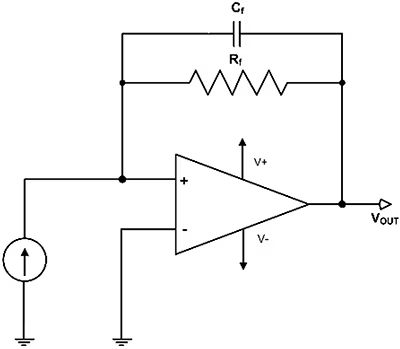
Figure 2: A TIA converts a current input into a voltage output proportional to the value of the feedback resistor. (Image source: Art Pini)
Applications of Low VCR Resistors:
Low VCR chip resistors are used in LED lighting, medical instrumentation, audiovisual equipment, sensing systems, and high-voltage or pulsating-current communications.
A typical example is the transimpedance amplifier (TIA), which converts an input current signal (IIN) into an output voltage (VOUT) proportional to the feedback resistance (Rf).
In applications with photodiodes, accelerometers, photomultiplier tubes (PMTs), or piezoelectric sensors, the linearity of the system depends on the resistive stability under voltage. Any variation in the Rf value due to the VCR introduces nonlinear gain modulation, generating second-order harmonic distortion and degrading measurement accuracy.
Another common application is the resistive voltage divider, used to attenuate high-voltage or high-frequency signals before delivering them to control, sampling, or measurement stages (Figure 3). In these cases, a low VCR prevents the attenuation ratio from varying with the voltage level, ensuring measurement accuracy and reducing linearity errors.
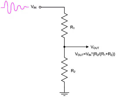
Figure 3: Low VCR resistors are used in voltage divider circuits; these reduce the voltage level of a signal and are typically used to feed a high voltage back to a device with a lower nominal input voltage. (Image source: Art Pini)
Examples of Low VCR HV Resistors:
RVCU series includes thick-film chip resistors designed to withstand working voltages between 800 V and 3,000 V, with exceptional voltage stability. They are available with tolerances from 0.5% to 5%, in ranges from 75 kΩ to 30 MΩ, and feature VCRs as low as ±25 ppm/V (up to 3 MΩ) or ±50 ppm/V (up to 30 MΩ).
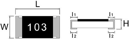
Figure 4: The mechanical dimensions of the RVCU series of surface-mount chip resistors are shown. (Image source: Stackpole Electronics Inc.)
These resistors comply with AEC-Q200 for automotive applications and with ASTM-B-809 sulfur resistance testing.
Standard SMD packages 1206, 2010, and 2512 (3216, 5025, and 6332 metric, respectively) allow for direct integration into printed circuit boards (PCBs). Power dissipation ranges from 0.33 W to 1 W, with maximum overload voltages from 1,000 V to 4,000 V, depending on the package.
Conclusion:
In high-impedance, high-voltage, or precision-critical electronic circuits, selecting resistors with low VCR is essential to ensure linearity, stability, and accuracy.
The Stackpole RVCU series offers surface-mount (SMD) components with VCRs between 25 and 50 ppm/V, ideal for instrumentation, power control, analog-to-digital conversion, and precision sensing, ensuring reliable performance in applications up to 3,000 volts.
Author: Rolf Horn