

Introduction
A PDN must deliver stable voltage and sufficient current to all components of a PCB or system. With increasing switching speeds and decreasing supply voltages, challenges arise such as:
High-frequency noise from switched-mode regulators or digital logic.
Voltage ripple due to fast current transients.
EMI that can affect sensitive circuits or cause regulatory compliance failures.
Ferrites exhibit frequency-dependent impedance, allowing DC current to pass while blocking high-frequency noise, making them ideal for:
Filtering power rails,
improving signal integrity
, and reducing EMI.
How ferrites work:
A ferrite bead behaves like a series inductor with high-frequency losses. Its impedance Z(f) increases with frequency:
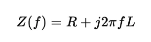
Low frequency/DC: R≈0
, the voltage is supplied without losses.
High frequency: R increases, blocking noise.
Typical applications:
1. High-speed digital circuits:
Modern FPGAs, SoCs, or microprocessors switch at hundreds of MHz–GHz.
Ferrite in series with the power rails of sensitive ICs reduces switching noise.
It is recommended to combine it with decoupling capacitors for broadband filtering.
2. Mixed (analog + digital) systems:
Ferrites separate digital and analog power supplies, reducing coupling and crosstalk.
They maintain signal integrity in ADCs, DACs, or RF front-ends.
3. EMI/EMC Compliance:
Placing ferrites near noisy ICs or in cables/harnesses reduces radiated emissions.
It improves electromagnetic compatibility without affecting system operation.
4. Switched-
mode power supplies (SMPS): SMPS outputs can contain high-frequency ripple.
Series ferrites reduce ripple and allow for a cleaner supply.
Design Considerations
When selecting ferrites, consider:
Parameter Recommendation
Impedance vs. Frequency Peak impedance at the noise frequency to be suppressed
Maximum DC current Ensure the core does not saturate
Voltage Drop Do not exceed acceptable voltage drop for the load
Power Dissipation Check heat generated by high-frequency losses
Combination with Capacitors Always use with capacitors for broadband filtering
Design tip:
Power supply → Ferrite → Capacitors → IC
Practical example
FPGA with 1.2 V rail:
Average consumption: 5 A, peak di/dt: 20 A/µs
Without ferrite: 50–100 mV ripple
With ferrite: 600 Ω bead reduces noise >10 MHz, DC drop
Capacitors: 100 nF + 10 µF to smooth the rest
Figure 2 – PDN with ferrite for FPGA:
Vin 1.2V ──> Ferrite 600Ω ──> [10 µF || 100 nF] ──> FPGA Core
│
└─> GND
Result: clean and stable power supply, without compromising high-speed current response.
Table 2 – Typical PDN Bead Examples:
Model Ferrite Maximum Current Impedance 100 MHz Typical Application
Murata BLM18AG600SN1 6 A 600 Ω FPGA, SoC
TDK MMZ1608Y601A 3 A 600 Ω Sensors, ADC/DAC
Wurth 742792060 5 A 600 Ω SMPS, High-Speed Digital Rail
Conclusion:
Ferrites are essential for modern PDN design:
They suppress high-frequency noise,
isolate sensitive subsystems,
reduce EMI, and facilitate regulatory compliance.
They are not universal: they require correct selection of impedance, current, and voltage drop. Combined with capacitors and good PCB practices, they improve the reliability and performance of complex systems.
References:
Ott, Henry W., Electromagnetic Compatibility Engineering, Wiley, 2nd Ed., 2009.
Howard Johnson, High-Speed Signal Propagation, Prentice Hall, 2003.
Analog Devices, AN-877, “Power Distribution Networks and Decoupling Techniques”, 2020.