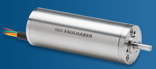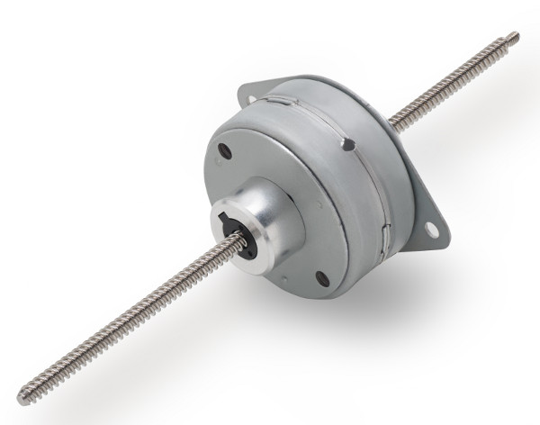


We will also look at some of the available motor controllers (in IC) from major suppliers, as well as suitable resources for development and prototyping.
Applications for Brushless Motors:
Over the last decade, brushless DC motors have become incredibly popular. One could say they are even more ubiquitous than Wi-Fi; we might be surprised to learn how many of these motors we find in our homes, cars, or offices. According to Allied Market Research, the global market for brushless DC motors will reach $72.2 billion by 2030, an increase of $33.2 billion compared to 2020 (Figure 1). According to their study, "Brushless DC Motors Market Research, 2030," the CAGR will rise by 10.3% across all motors, with 750-3000 W motors experiencing a particularly sharp increase.
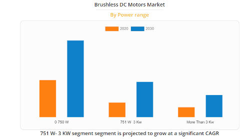
Figure 1: Growth in Brushless DC Motors 2020-2030 according to the Allied Market Research report (source: AMR - https://www.alliedmarketresearch.com/brushless-dc-motors-market - permission requested).
Brushless DC motors can be used in various applications: battery-powered tools, household vacuum cleaners, radio-controlled drones, electric vehicles, etc. In the industrial sector, their use is widespread in environments such as conveyor belts and production robots.
Brushless DC motors are so popular because they require minimal maintenance. They have a high level of energy efficiency: typically up to 92%, 10-15 percentage points higher than a similarly sized brushed motor. Furthermore, these motors can operate at high speeds due to the lack of friction caused by brushes. The absence of brushes also allows them to be smaller, quieter, and generate less EMI. All of this means they are the ideal component for drivetrains in electric vehicles, where high torque and speed are essential.
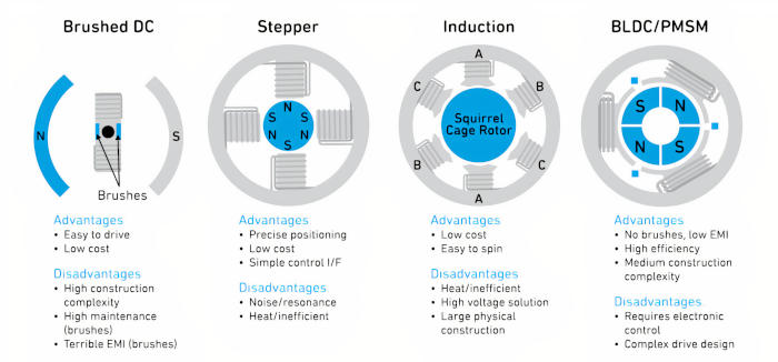
On the other hand, these motors are more expensive and require more complex control, so a balance must be struck between this and the advantages we've discussed. Figure 2 shows a comparison of the most common motor configurations, highlighting their advantages and disadvantages. Brushless DC motors are similar to permanent magnet synchronous motors (PMS), although there are slight differences in their operation and the internal construction of the stator windings.

Image 2: Most common types of DC motors, with their advantages and disadvantages (source: Qorvo)
How does a brushless DC motor work?
Before we delve into the operation of a brushless DC motor, or a brushless motor-
independent motor (MSIP), let's review some basic motor-related terms. Windings: These are copper coils placed on the rotor or stator. They function as electromagnets and generate a magnetic field according to the direction of the current flow. The three windings of the brushless DC motor in Figure 2 can be connected in series to create a single-phase motor or individually to create a three-phase motor.
Rotor: This is the rotating part of the motor. In a brushed motor, the windings around the rotor receive power through the brushes. In a brushless motor, the windings are located on the stator, and permanent magnets are placed around the rotor. There is a small air gap (known as the air gap) between the rotor and the stator.
Stator: This is the stationary part of the motor structure. In Figure 2, the magnetic poles of the stator in a brushed motor are visible; in a brushless model, the stator contains the non-rotating windings.
Commutation: the method used to change the direction of the current in a winding to achieve rotation.
Back electromotive force (EMF): the electrical energy created in a winding when it passes through a magnetic field. In brushless DC motors, this force comes from the permanent magnets in the rotor. The back EMF can be used to detect the rotor's position relative to the stator windings in order to control the commutation process.
The main difference between a brushless DC motor and an MSI is the shape of the stator windings and, consequently, the characteristics of the back EMF waveform (Figure 3).

Image 3: Comparison between the back electromotive force waveforms created by a brushless DC motor and an MSIP (source: Qorvo)
Sensors and Algorithms for Motor Control
To achieve rotation in a brushless DC motor or an MSIP, we must generate commutation using control signals applied to the stator windings. Semiconductor motor controllers (or drivers) create waveforms, the number and shape of which depend on the motor type and the number of phases. Figure 3 shows a brushless DC motor controlled with a trapezoidal waveform, in contrast to the sinusoidal method with field-oriented control (FOC) in an MSIP. In a three-phase MSIP, commutation uses three sinusoidal waveforms with a 120° phase shift between them. A brushless DC motor can also be controlled with a sinusoidal waveform.
To correctly control the rotor, whether using FOC or trapezoidal control, we must know its exact relative position with respect to the stator windings. The motor controller receives this essential information, allowing it to control the motor's speed and torque. The position data determines the frequency, periods, sequence, and control signals.
There are two methods for determining rotor position: with and without a sensor.
With a sensor: Hall effect sensors are placed next to each of the stator windings (the small blue boxes in Figure 2) to detect changes in the magnetic field polarity (N to S and S to N) as the rotor turns. A three-phase motor requires three sensors.
Without a sensor: Instead of using sensors, the rotor position is determined by the back electromotive force (EMF).
Both methods have advantages and disadvantages. Using Hall effect sensors requires additional components (increasing the cost) and slows down construction. However, sensor-driven motors (both brushless DC and MSIP) offer excellent torque and efficiency, as well as very smooth rotation. The controller for an MSIP is typically more complex, and if FOC control is used, sensors are necessary.
The sensorless method is the most common for brushless DC motors. The advantage is that the price is very attractive, but to determine the rotor position using the back electromotive force (EMF) induced in the stator windings, we need algorithms. One of the problems with using a sensorless method in brushless DC motors occurs during startup. When there is no movement, there is no back EMF, so the rotor position must be determined by another method. Typically, high-frequency control signals are applied to each phase winding, and an algorithm calculates the corresponding position.
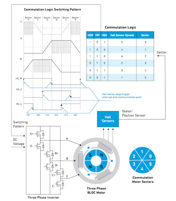
Image 4: Simplified diagram of a three-phase brushless DC motor with Hall effect sensors for commutation and sequencing of inverter operation (source: Qorvo)
Figure 4 shows a simple configuration of a three-phase brushless DC motor with Hall effect sensors (HSW, HSV, and HSU). The sensors are essentially digital switches and indicate the polarity of the detected magnetic field (north is 1 and south is 0). The outputs of the three sensors are combined to generate a three-bit digital logic code that indicates the rotor's position and direction of rotation. This information forms the basis of the control signals for the inverter stage of the three-phase power transistor. In low-power brushless DC motor applications, the sensor interface, motor driver, and control transistors are typically integrated into a single driver IC. More powerful motors typically take the gate output of the driver IC and use a heatsinked power MOSFET to achieve the desired control current.
To vary the motor speed, pulse-width modulation (PWM) changes the duty cycle: the frequency of the on/off switching. This method is also useful during engine start-up to limit the starting current.
Brushless DC Motor Drivers and Development Resources
Figure 5 shows the functional block diagram of the TI DRV10963. It includes three power MOSFETs and can be used with motors up to 5 V/0.5 A for controlling cooling fans in laptops and high-performance processors. The DRV10963 protects against overcurrent and short circuits by monitoring the current and voltage of each MOSFET with a multiplexed analog-to-digital converter (ADC). A PWM input can control the motor speed to achieve the desired speed. The FR input allows the motor direction to be reversed at startup, and the FG output provides information about the motor speed.

Figure 5: Functional block diagram of the TI DRV10963 for a sensorless, three-phase, 5V brushless DC motor driver (source: TI)
Microchip offers a full range of integrated circuits (ICs) for brushless DC motor and gate drivers. One example is the MCP8063, a sensorless, three-phase, brushless sinusoidal motor driver designed for automotive cooling fans and pumps. The Qorvo PAC5532 power application controller is an excellent choice for a wide range of high-speed motor control applications in the automotive, industrial, and consumer sectors, such as battery-powered tools, e-bikes, and hybrid electric light vehicles. The PAC5532 can be used with 48–120 VDC systems and contains a 32-bit, 150 MHz Arm Cortex-M4F core with configurable and comprehensive power management and control functions (Figure 6).

Figure 6: Simplified block diagram of the Qorvo PAC5532 in battery-powered motor control applications (source: Qorvo)
The PAC5532 can be complemented with the Qorvo PAC5532EVK1 evaluation kit .

Figure 7 (source: Qorvo) shows the main components of the evaluation kit, including the PAC5532 and the half-H-bridge inverter components. A GUI-based software development kit is available for download from the Qorvo website.
Another motor control IC is the Renesas RA6T2. This IC features a 240 MHz Arm Cortex-M33 microcontroller core and includes a hardware accelerator to speed up complex motor control algorithms and execute secure cryptographic functions. It also boasts a comprehensive set of analog functions, including a 12-bit analog-to-digital converter (ADC), a 12-bit digital-to-analog converter (DAC), programmable gain amplifiers, and high-speed comparators (Figure 8).

Image 8: Functional block diagram of the motor controller IC with RA6T2 microcontroller (source: Renesas)
The Renesas MCK-RA6T2 evaluation kit offers a practical method for prototyping brushless motor controller designs. It consists of three breadboards (inverter, microcontroller, and communications), a small brushless DC motor, and all necessary cables. The functional architecture of the MCK-RA6T2 is shown in Figure 9.

Image 9: Functional block diagram of the Renesas MCK-RA6T2 brushless motor evaluation kit (source: Renesas)
TheFirst Steps in Brushless DC Motor Control
In this short article, we've seen how brushless DC motors work, explored their popularity, and discussed some use cases. The main semiconductor solutions described in this section provide a practical, reliable, and well-documented tool for getting started with brushless DC motor (BDC) or brushless iMP motor (BIM) designs.
Author: Mark Patrick, Mouser Electronics