


It is common for an AVV (Automatic Vehicle Variable) system to use commercially available microcontrollers or digital signal processors to implement processing and control loops, which can monitor the load and directly control motor torque, speed, position, and other drive-related aspects. However, these devices are limited by their lack of scalability and performance when processing increasingly complex algorithms in support of multi-axis devices. Currently, motor controllers must be networked to support industrial automation, but microcontrollers and digital signal processors lack the flexibility needed to comply with the wide variety of existing industrial networking standards.
 Designers are now turning their attention to FPGAs for next-generation AVV systems due to their inherent flexibility and performance, as well as the advantages they offer in terms of integration and design flow. However, many motor control engineers specialize in DSP software or algorithms and are not RTL designers familiar with FPGA-based design.
To overcome this mismatch caused by the need for specialization, model-based design techniques such as MATLAB/Simulink have been used for better modeling of these algorithms. Along with block-based design tools, such as Altera's DSP Builder Advanced block set, DSP designers can work within a familiar MATLAB environment and automatically generate an optimized RTL. DSP Builder can time-share logical operators such as multipliers and adders and supports both floating-point and fixed-point arithmetic directly in hardware. Variable-precision DSP blocks on the FPGA can handle the precise timing engine algorithm with its fixed-point and floating-point DSP and can easily implement computationally intensive operations such as field-oriented control (FOC).
Another inherent advantage of an FPGA is its ability to integrate most of the functional blocks of a motor control system due to its capacity to process control loops and support parallel management. Embedded processors such as the Altera® Nios® II (32-bit RISC software processor) can control the various I/Os, as well as provide filtering and connectivity to external sensors or devices with any digital interface standard; for example, sigma-delta, BISS, ENDAT, or Hyperface encoders, etc. With a Nios II processor and a custom Ethernet MAC, it is even possible to implement a deterministic Industrial Ethernet protocol such as EtherCAT or PROFINET. Since the FPGA is programmable, it is possible to reconfigure the device and implement support for any sensor interface or Industrial Ethernet standard without changing the physical hardware. This flexibility is a key advantage of using FPGA devices.
The ability of an FPGA to support any industrial Ethernet (or serial fieldbus) standard also means that developers can easily integrate any safety protocol standard or stack into the drive. Altera recently announced the availability of a safety data package for its FPGA devices and development tools. This allows developers to integrate safety-related functionality into the same FPGA as the drive controller, further reducing costs. Pre-certification of the FPGA development workflow, development tools, and device reliability data significantly reduces development and safety approval time.
 In the system shown in Figure 2, the system's safety section is implemented using two safety controllers. This redundancy serves as protection against system safety failures. By comparing the outputs of each safety controller, any failure in one controller will be detected, and the system will be able to execute an appropriate safety shutdown. The second safety controller can be implemented on another FPGA or a microcontroller.
Advantages of FPGAs for Implementing DSP Algorithms
FPGAs offer numerous advantages in terms of performance, such as:
1. Faster operation and processing speed thanks to the parallelism of the FPGA hardware and scalability to larger devices if needed.
2. Reduced waiting time due to the potential hardware acceleration of tasks previously implemented in software and the direct interface between the control loop algorithm and its peripheral interfaces (A/D converter, PWM, position encoder, etc.) through integration within the FPGA itself.
3. Unchanging waiting time for hardware-implemented algorithms. Waiting times in software implementations can be difficult to predict and can cause real-time problems if not properly managed.
4. Synthesizing a high-level Simulink design directly to an FPGA implementation using DSP Builder does not require advanced HDL knowledge from the algorithm designer.
- The use of the unfolding function allows for compensation of waiting time, processing speed, and resource allocation.
- Support for variable-precision floating-point and fixed-point arithmetic allows for algorithm optimization.
 Migrating Existing C Code to an FPGA Platform:
Designers can migrate applications to FPGAs using existing C code once it has been ported to a Nios II embedded processor. The code can be profiled to address CPU-intensive bottlenecks or offload real-time tasks to the FPGA, freeing up the processor to handle other tasks. Designers can offload functions by creating custom, hand-written RTL-based instructions or generating DSP hardware accelerators using DSP Builder.
For new designs, designers can use Simulink from the outset to model the entire system with blocks divided between software, DSP hardware accelerators, or custom RTL IP (peripheral interfaces, etc.).
DSP Builder's Advanced Block Set
adds specialized Simulink libraries to the MATLAB design environment, enabling designers to quickly and easily implement DSP designs. The Advanced Block Set is based on high-level synthesis technology that optimizes the netlist with no time limit and segments hardware for the target FPGA with the required clock speed. DSP Builder describes the hardware as VHDL, with scripts that integrate into the Quartus® II software flow and the ModelSim simulator.
When the system clock speed is faster than the data rate or sampling rate, a hardware block such as a multiplier can potentially reprocess multiple data points. DSP Builder describes the ratio of clock speed to sampling rate as the "fold factor." When designers enable fold in DSP Builder, multiple data points can access the shared hardware block, resulting in resource savings.
 Typical example of motor control, tests, and results:
Field-oriented control (FOC) must be able to control a three-phase sinusoidal motor current in real time to create a smoothly rotating magnetic flux pattern, where the rotational frequency corresponds to the frequency of the sinusoidal waves.
The technique controls the amplitude of the current vector at 90 degrees to the rotor's magnetic flux axis (quadrature current) to
control the torque and maintain the direct current component (0 degrees) at zero.
This solution also includes proportional-integral (PI) position and speed control loops to enable control of rotor speed and angle. The interface IP required to complete the design shown in Figure 1 can be easily obtained using Altera's SOPC Builder tool.
In a typical FOC controller, the software samples inputs at 10–100 ksps, and the FPGA clock speed is 50–100 MHz. At 100 ksps, a new sample must be processed in less than 10 µs. Keeping this waiting time constant and to a minimum is beneficial for the performance of the control algorithm.
 Once the algorithm is modeled in Simulink using single-precision floating-point notation and with the expected performance, the hardware is generated to create the VHDL interconnect list for the chosen FPGA using a target clock speed of 100 MHz. DSP Builder directly indicates the algorithm's wait time along with an estimate of the resources used. To obtain the precise resource utilization, the design is then compiled using Quartus II software.
A design of this type is suitable for fixed-point implementation, although floating-point notation can offer numerous advantages to designers:
Avoid the burden of arithmetic calculations and scaling problems, thus reducing development time.
Superior performance thanks to its inherent numerical stability.
Potentially faster control loop responses due to the high dynamic range.
Altera's FPGAs and development tools can support both fixed-point and floating-point solutions.
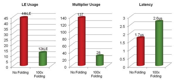
 By default, DSP Builder creates a fully segmented representation that can accept new input values on each clock cycle. The designers compare the result obtained with this configuration to a configuration with splitting (see Figure 3). The designers also compare it with the same algorithm implemented in fixed-point and floating-point formats (see Figure 4).
The results shown below demonstrate how splitting significantly reduces the operator count, allowing the use of a much smaller Cyclone IV device with a longer wait time, while still remaining acceptable for the algorithm. The control loop speed is the sum of the algorithm's wait time and settling time. 200k PWM loops or outputs per second are obtained in 5 microseconds, thus meeting the required specification.
Summary of Results
1. With splitting:
- Reduces the use of logic elements (LEs) and the multiplier, allowing for a much smaller FPGA.
- Increases wait time but remains acceptable for the algorithm.
- Reduces the processing speed to 1 Msps, which is still 10 times faster than the 100 ksps required for FOC.
- Allows the solution to process up to 10 channels of the FOC algorithm in real time.
2. 32-bit floating-point and fixed-point use resources similarly, but the wait time for fixed-point is almost half. Without splitting, there is a much greater difference in resource usage between floating-point and fixed-point.
3. Reducing the precision to 16 bits reduces the required resources due to the narrower data path.
Abstract:
Current microcontrollers and digital signal processors are being pushed beyond their capabilities for next-generation motion controllers. FPGAs offer the perfect platform for motion control because they provide:
- Flexibility to integrate all functionality into a single device.
- Approved development workflows, tools, and IP addresses for security, as well as device reliability data.
- Scalable capabilities to process multiple channels and support high-precision floating-point operations.
- Access to embedded processors, networks, and interface IP for peripherals and system solutions, enabling quick and easy system integration.
Many design engineers are unfamiliar with using FPGAs in DSP applications, making it important to provide tools that can increase efficiency and reduce development time. Altera has developed a suite of tools, such as SOPC Builder and DSP Builder, that allow users to leverage conventional DSP development workflows and quickly generate their next-generation motor control systems.
Author:
Kevin Smith, Design Engineer, Senior MTS, Altera.