- Low tip capacitance. The ISOVP probe was designed to minimize tip capacitance, as this is what impairs most high-frequency measurements. For a given source impedance, the tip capacitance acts as a low-pass filter, attenuating the output signal at high frequencies. Therefore, tip capacitance should be as important a selection parameter as bandwidth when choosing a probe.
- Low common-mode load. Since the optical probe is completely isolated from the environment, the only common-mode capacitance is the parasitic capacitance from the probe to the environment. It is important to keep the common-mode capacitance as small as possible, as voltage transients will produce common-mode currents. Due to the small size of the ISOVP probe, this capacitance was measured at around 1.5 pF from the probe to a ground plane at a distance of 10 cm. This capacitance can be made even smaller if the user chooses a different configuration.
- Floating measurements. Floating measurements have become an important part of modern and power electronics, since the gate voltages of switching elements (IGBTs, MOSFETs, thyristors, etc.) must be measured for their reliable operation, and modern topologies often stack these semiconductors to handle higher voltages. Given the appropriate separation distances between the probe head and the chassis, optical probes can safely float up to tens of kV.
- High common-mode rejection. In power electronics, not only are high common-mode voltages the norm, but they are also rapidly changing. This is where the common-mode loading and fiber isolation advantages of optical probes come into play. Differential probes have a limited rejection ratio that decreases rapidly with increasing frequency, while optical probes offer improved rejection.
- Selectable cable length. Up to 15 m of fiber optic cable can be placed between the probe head and the receiver.
- Hot calibration of zero and gain. Due to drift and temperature changes, optical links need to be calibrated. The ISOVP calibrates the signal offset and amplitude while the source remains connected. This increases user safety, as it eliminates the need to access potentially hazardous areas.
- Remote standby and shutdown. To increase user safety and battery life, both the probe head and receiver can be put into standby mode at the touch of a button.
- Compatibility with all oscilloscopes. The ISOVP probe can be connected to any oscilloscope using a BNC cable. An internal 50 Ohm termination is required for proper probe operation, but even oscilloscopes without this feature can use the probe with an external 50 Ohm power supply. An optional external termination is available (code ISOVPTERM).
Differential probes have been the cornerstone of floating voltage measurement. However, they are not true isolated devices; their bandwidth is modest, and their common-mode rejection is limited by both high-frequency signals and sources with mismatched impedance. Furthermore, they are often noisy and unsuitable for measuring low voltage values. As an additional observation, it should be noted that some high-voltage differential probes can exhibit significantly degraded common-mode rejection after some time. This is due to an incorrect substrate selection in the high-impedance divider section, which can change its dielectric properties without the user's ability to adjust it.
Typical Measurements with the ISOVP Probe:
The maximum differential input voltage of the ISOVP is specified as ±2.5V, although it will not saturate for slightly higher inputs. The included x10 and x50 attenuators extend the input range to cover most practical measurement needs.
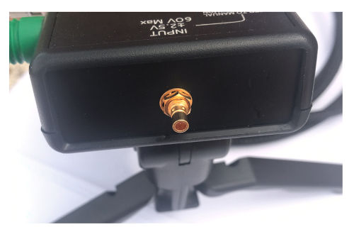
The input connector for the ISOVP probe and attenuators is an SMB RF type, which is convenient for its ease of use, as it is widely available, requires no torque wrench, and can be connected to common RG174 or similar coaxial cables. Saker recommends using good quality SMB connectors, such as Radiall part number R114082000.
When manually attaching the probe head, be aware that the unit is physically attached to the receiver unit, so pulling on the probe head could accidentally drop the receiver. Also, be careful not to trip over the fiber optic cable connecting the receiver and probe head, as this will likely cause both units to fall and could result in unit failure.
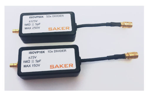 Attenuators are included with the ISOVP probe.
It is always recommended to mount the probe head on a tripod stand. This will give the probe mechanical stability and ensure adequate clearance between the probe and its surroundings. Always remember that all metal parts of the probe head are at the same potential.
The ISOVP unit is supplied with two adapter cables, one with mini-cable recorders and the other unterminated, allowing the user to make the appropriate connection for their specific setup. The mini-cable recorders easily connect to thin wires or small IC pins, such as those on the SO-8 package. The unterminated SMB cable allows the user to make additional terminations. In most measurement scenarios, a typical 2.54 mm straight header installed on the board will provide a sufficient connection. Additional unterminated SMB cables are available (part number ISOVPUC).
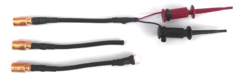 Top and center: SMB cable with mini-clamps and unterminated SMD cable (included with the ISOVP probe). Bottom: Customer adaptation of an SMB cable to a 2.54 mm straight pin cable.
Securely place the probe head on a surface to prevent accidental falls; use plastic securing straps if necessary. Once all electrical connections are made, switch on both probes. The receiver can be placed in a safe, low-voltage area. To conserve battery power, it is recommended to put both the probe and receiver into standby mode via the receiver whenever measurements are not required. This can be done by simply pressing a button on the receiver. Also, calibrate the probe using the CAL button before taking range measurements, and do so periodically if needed
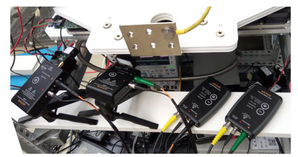 Two ISOVP probes with x10 attenuators measuring IGBT gate voltages in a medium-voltage multilevel inverter. Note the use of tripods on the probe heads (image provided by the customer)
Ambient temperature changes rapidly. The ISOVP supports hot calibrations so you don't have to disconnect the DUT (device under test).
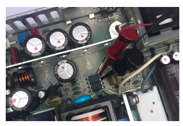 Testing an optocoupler with the supplied mini-recorders
Remember that the receiver requires a 50 Ohm load for the probe to calibrate. If calibration fails, check that the center pin of the oscilloscope's input BNC connector is making good contact with the supplied BNC cable.
Low-Level Measurements:
The ISOVP probe is well-suited for measuring low-level signals, especially when using a digital oscilloscope with excessive bandwidth and sampling rate.
The 10x attenuation inherent in the ISOVP probe increases the noise displayed on the oscilloscope relative to the signal. However, modern digital oscilloscopes feature a useful high-resolution mode that will eliminate most of the noise from the signal. Furthermore, while 8-bit digital oscilloscopes were traditionally the norm, oscilloscopes with 12-bit and 14-bit ADCs are becoming increasingly common. All of these features result in clearer signals and greater noise reduction.
As an example, we generated a 10mVpp, 10kHz square wave and fed it into the ISOVP probe without attenuation. The 8-bit oscilloscope was set to High-Res mode, and the measurement result can be seen in the following image. With 10, 12, or 14-bit oscilloscopes, the improvement would be more noticeable. Measuring low levels like this can be useful for noise and ripple measurements.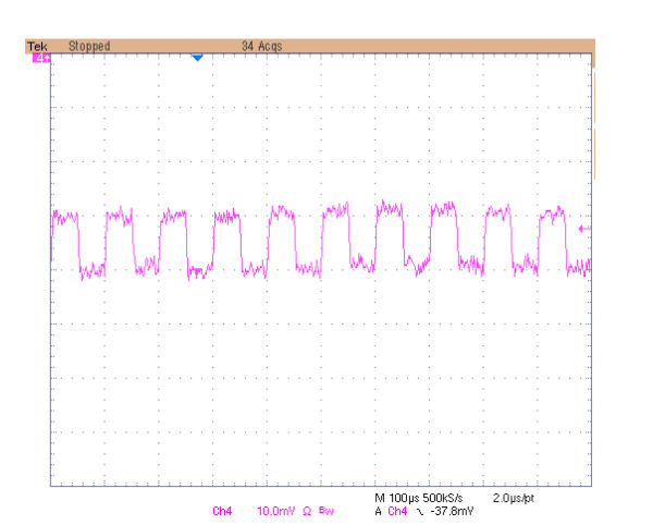
10kHz 10mVpp signal input to the ISOVP probe with the oscilloscope in Hi-Res mode
Ripple Measurements:
Ripple can be a sign of potential design and reliability problems in some systems. Ripple is typically mounted on a DC level, and most oscilloscopes have limited DC compensation capability when the vertical scale is set to a more sensitive setting. Power lines or lines where switching spikes interfere could be the target of ripple measurements.
To aid in these measurements, Saker offers an external DC blocking capacitor (order code ISOVPDC) with SMB input/connectors. It contains a 1µF 500V capacitor, a DC voltage sufficient for most practical applications. The AC voltage limit for this accessory is 20Vpk, and it is there to protect the input of the next stage.
Measuring high voltages with commercial probes and ISOVP:
The maximum voltage measurable with the ISOVP using the included attenuators is limited to approximately 130V. However, there are practical situations where a user may need to measure higher voltages, such as those found across bus capacitors, IGBT Vce, or floating inductors.
The ISOVP probe's input impedance is specified as 1 MΩ with a small parallel capacitance. This mimics the impedance seen on oscilloscopes, making the probe well-suited for use with third-party probes, such as the common x10, x100, and x1000 passive probes available on the market. The use of high-voltage x1000 probes is of particular interest due to the wide measurement range they provide.
A well-known x1000 probe on the market is the Tektronix P6015A, with an input impedance of 100 MΩ, 3 pF, and a bandwidth of 75 MHz. Using this probe also introduces some delay, 15 ns for a 10-foot cable. The output compensation box can accommodate oscilloscopes with an input capacitance of 7 to 49 pF. For proper pulse accuracy, it is crucial to adjust the probe compensation box to match the pulse response of the specific oscilloscope being used. A 1000V square wave or higher should be used for this adjustment.
A probe like the P6015A can be connected directly to the ISOVP probe or via the x10 or x50 attenuators. Together, these will allow the user to perform safe float and high-voltage measurements. The ISOVP probe's 6pF input capacitance, plus the approximately 4pF added by a BNC RF Tee adapter, will bring the P6015A's compensation box within its adjustment range.
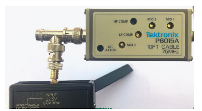 Connecting a 1000x probe via a BNC T-connector. Other probe types can be connected in the same way. The additional BNC port can be used to add extra compensation capability if the probe requires it.
Measuring Floating Signals with High Common-Mode Voltages:
Measurements with differences between grounds, or common-mode voltages, are called floating measurements and are said to float by the amount of common-mode voltage. An ideal floating measurement would be insensitive to common-mode signals. Common-mode voltages can be fairly constant over time or vary rapidly, as occurs in modern switched-mode converters.
Modern power electronic topologies rely heavily on switching semiconductors that are stacked to handle higher voltages. Topologies such as CHB, NPC, or typical H-bridges are examples of this type. In this environment, floating measurements are essential for proper troubleshooting, but most probes are referenced to ground, leaving the user with only the choice of differential probes and their limitations, or oscilloscope floating, with its inherent risks.
Although some measurements appear to be referenced to ground, it is better to consider them as floating measurements, since the parasitic inductance and resistance of one of the ground probe points greatly affect the measurement in high current or fast pulse systems.
In general, the following parameters should be considered when performing measurements while floating:
● Differential voltage between sounding points.
● Source impedance at the sounding terminals
● Maximum common-mode voltage.
● Maximum rotational speed of the common-mode voltage.
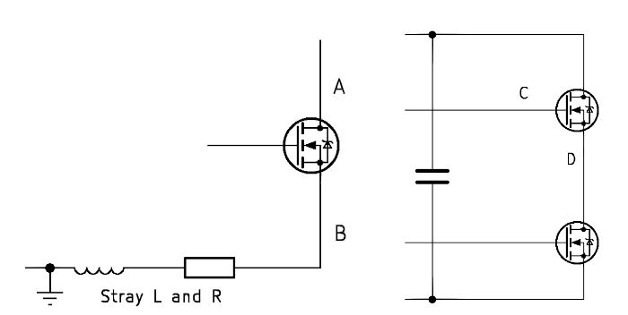 The measurement from A to B will be greatly affected by the high currents and voltages pulsed by parasitic L and R if taken as a ground-referenced measurement. The measurement of the high-side gate voltage from C to D is typical in power electronics and will require a probe with the appropriate capacity not only for that particular common-mode voltage but also for the switching speeds created by the LS (low-side) MOSFET.
Optical probes are especially useful for floating measurements, and the ISOVP probe can safely float at thousands of volts while only slightly charging the probe points.
The circuit shown in the following image was built as a test platform for generating large, fast-varying common modes. By limiting the MOSFET's switching current with a large drain resistor, it is possible to create high-speed, variable common-mode voltages. A 4.5kV MOSFET (IXTH02N450HV from Ixys) was used in these tests. A 40kHz oscillator powered by a 1.5V battery is floating on the MOSFET's drain, and the ISOVP probe is configured to measure this voltage directly without attenuators.
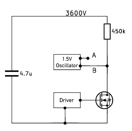 A test circuit for generating rapidly varying medium-voltage common modes is also shown. Measuring a 1.5Vpp signal at a voltage of 3.6kV presents a challenge for any researcher. The oscillator and the driver are not synchronized.
Test circuit measurements. CH2: 1.5V oscillator output (AB) measured with the ISOVP probe. CH3: MOSFET Vgs. CH4: MOSFET Vds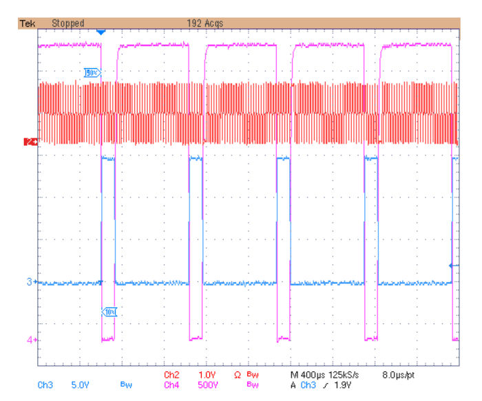
Detailed view of the switching pulse. To the left of the falling edge of CH4, the oscillator (CH2) is floating at 3.6kV and almost 0 to its right. Such a low voltage measurement is nearly impossible to perform with a differential probe given the high common-mode noise of the signal.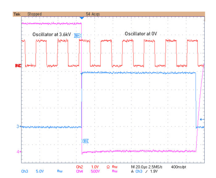
When performing these types of measurements, it is important to maintain a sufficient distance between the probe and any metal parts near the circuit. The faster the dV/dt, the greater the leakage current for a given common-mode capacitance.
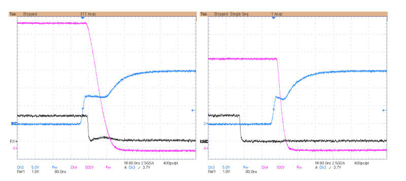 Left: Detail of the MOSFET drain falling edge. CH3: Vgs MOSFET. CH4: Vds MOSFET, with a slew rate greater than 35kV/µs.
R1: Oscillator output captured with a slight distortion of 0.2V
due to common-mode interference at switching time.
Right: Same measurement as the graph on the left, but with 500V instead of 3600
Regarding the CMRR of probes:
A perfect probe would detect only the desired voltage component and reject all the common-mode voltage component. Generally, ground-referenced probes cannot be used when common modes are present unless the oscilloscope itself is isolated. Therefore, the traditional solution has been the differential probe.
The common-mode rejection ratio is a measure of how much the amplifier rejects the common-mode voltage relative to the differential voltage. Differential probes are known to have a less than admirable CMRR at high frequencies, and the problem worsens if the source impedance is uneven. In optical probes, the amplifier is single-ended, and since it is floating and there is no ground return, an imbalance in the source impedances does not worsen the CMRR.
Typically, the CMRR decreases as the frequency increases. For historical and ease of use, CMRR has been measured using a variable-frequency tone. However, in real-world applications, no one measures pure sine waves, but rather pulsed signals with multiple frequency components. In reality, a performance metric based on slew rate would be more useful for the developer.
In practice, CMRR versus frequency measurements are primarily used to compare performance across different manufacturers and as a marketing tool. However, even for this application, they are tools with shortcomings. For one, there is no clear, standardized test setup that manufacturers must adhere to, such as the power level of the tone applied as a common-mode signal. CMRR also depends on the probe's input voltage range; that is, CMRR values would differ for probes with an input range of ±0.5V, ±1V, or ±10V. Finally, some manufacturers include the probe's inherent attenuation in the CMRR to make the numbers appear more favorable.
General measurement tips and tricks
: Remember the key values for each measurement. Each time a measurement is taken with the ISOVP probe, the most relevant values must be considered. These values must be compared to avoid exceeding the maximum values of the attenuators and the probe, thus ensuring personnel safety.
- Maximum differential voltage to be measured
- Common-
mode voltage of the source - Common-mode voltage switching frequency - Source impedances
- Ensure the probe head and receiver are secure. Both units are connected by fiber optic cables, so care must be taken when manually positioning one unit, as the other could be accidentally knocked over. Furthermore, when positioning both units, it is possible to trip over the fiber optic cables. Therefore, it is advisable, for example, to secure the probe head tripod with plastic, a Velcro strap, or something similar. Both units contain sensitive electro-optical components that can be damaged by mechanical shock.
- Maintain safe distances. The entire probe head is optically shielded and can potentially float at thousands of volts. A maximum of 50 kV has been tested for the ISOVP. However, the user should ensure adequate clearance given the voltage and common-mode switching frequency. Higher common-mode frequencies will create larger ground leakage currents. Always use a non-conductive plastic tripod to increase the distance between the probe and any nearby conductive surfaces.
Keep probe connections short. General probing techniques apply when making measurements with the ISOVP probe. Increased care should be taken when making probe connections when circuits generate large dI/dt or dV/dt oscillations. Electric fields couple in unshielded lines, and magnetic fields create voltage differences in electrical loops. Therefore, it is generally best to transmit the measured signal over a coaxial cable for most of the distance between the probe points and the attenuator input. The supplied unterminated coaxial cable can be used to adapt specific coaxial-to-board terminations, such as coaxial connectors, 2-pin headers, or crimp ring terminals.
Don't forget standby mode. When the probe is not in use, use the standby function, which puts the receiver and probe head into low-power mode. Most of the time, measurements are only needed for a short period. The probe head must be battery-operated due to isolation requirements, and its power consumption is higher than that of the receiver due to optical transmission requirements.
- Use the auto-calibration function. This function adjusts the probe's offset and gain. Using this function only takes a few seconds and can be done at any time without disconnecting the input signal, so it is recommended to use it every few minutes and just before any important measurement.