
What drives the need for high-voltage switching?
Although relatively new, the electric vehicle (EV) sector has already achieved significant market penetration and sales. Furthermore, electrification is generating debates about the future of personal and public transportation. According to Statista.com:
• The EV market is projected to reach an impressive $784.2 billion worldwide by 2025.
• The market is expected to experience an average annual growth rate of 6.01% between 2025 and 2029, reaching a value of $990.4 billion in 2029.
• EV sales are expected to reach approximately 17.36 million units in 2029.
Current automotive bus architectures typically operate at 400V, but 800V bus systems are being introduced to increase power and/or reduce current. Some car manufacturers are considering using even higher voltages, as are manufacturers of commercial vehicles and those intended for public transportation. Battery systems exceeding 1000V are also being designed.
Other emerging markets are also driving increased system voltages. For example, renewable energy from solar installations requires the ability to handle high voltages during conversion, transmission, and storage. The medical field increasingly relies on high-voltage diagnostic imaging equipment, such as CT scanners and X-ray machines. Furthermore, traditional high-voltage applications, such as cable insulation, printed circuit board insulation, and semiconductor testers, continue to require high operating voltages.
Why 500V?
The point at which a system can be considered "high voltage" seems somewhat arbitrary. However, equipment manufacturers tend to agree that it is at least 400V. Why this figure? The fact is that systems operating at 250VAC, the industry standard, will reach a peak of around 350V. Manufacturers of modular switching products often require that all units exceeding 500V incorporate a hardware interlock feature to ensure safe operation. At these levels, suppression circuitry is necessary, and high-voltage connectors are generally advisable. Therefore, it seems reasonable to classify 500V as "high voltage."
At the extreme end of the scale, reed relays (which, as we will see in detail later, are very well suited for high-voltage switching) can offer breakout voltages of up to 15kV and even higher in certain designs.
Advantages of Modular Test Systems for High-Voltage Applications
Before delving into high-voltage switching, it's worth recalling why choosing a modular platform based on commercially available technologies and standards will help reduce the cost of a test system, shorten development time, and deliver a system that performs precisely what each specific application requires. Such a system will also help reduce testing time, as both hardware and software can be fully integrated and automated, optimizing testing processes and enabling multiple tests to run in parallel.
PXI is a standard test, measurement, and control platform based on an open architecture from the PXI Systems Alliance (PXISA), supported by over 60 vendors who manufacture, sell, and integrate PXI-based hardware and software solutions. With so many vendors offering compatible equipment, system designers can select the most suitable functional blocks from different companies, depending on the application requirements, rather than being limited to using products from a single vendor.
Using a standardized architecture also reduces the time needed to configure a test system for emerging products and requirements. Because of the flexible and scalable nature of PXI-based systems, both hardware and software, the modular system can grow as system complexity increases. Modular elements can be added as needed to increase functionality or capacity, minimizing the initial investment while protecting its value because it won't be wasted when testing requirements grow.
Best of all, test engineers aren't limited to using pre-configured systems from a single vendor. Such solutions often fall short of meeting all system requirements, or they are oversized and complex, exceeding the necessary capacity and incurring additional costs. In contrast, a test system based on the PXI standard can be flexible without being complicated.
Safety, reliability, and repeatability.
Returning to the topic of high voltage, safety, reliability, and repeatability are the three fundamental pillars upon which high-voltage switching systems must be based. Let's examine each of these in detail:
Safety:
When voltages can reach kilovolt levels, safety must be paramount. Therefore, high-voltage switching products should include a functional hardware interlock that can isolate their front-panel outputs, ensuring that all relays are deactivated. For example, a hardware interlock on a door switch can be used to disable a relay if the test system cabinet door is open. There are many possible configurations when using cards stacked on top of each other: several cards can be interconnected, with one managing the hardware interruption line, or they can be installed separately. Typically, this involves a switch on a cabinet door: if the door is open, the cards operate in safe mode, even if 5kV is applied. Similarly, when the door is open, and therefore the operator cannot touch anything energized, the cards switch to active mode and the system can be used normally.
The presence of high voltage also means that parasitic elements, interference, and spikes are more damaging, potentially creating safety and reliability issues. Therefore, suppression circuitry should be included. We will discuss this further in the next section.
Naturally, all equipment designed for high voltages must comply with international standards, such as IEC 62271-200 for high-voltage switchgear.
Reliability.
The reliability of high-voltage switching systems depends on the quality and selection of components. The switch itself is the most important element to consider; it is likely to be a relay. Although there are various types of relays, reed relays offer several advantages that make them ideal for high-voltage applications.
In electromechanical relays (EMRs), the contacts are open to the outside. This means that dust and other particles can contaminate the contact surfaces and negatively affect their performance. In contrast, reed relays incorporate a hermetically sealed switch whose contacts operate in a vacuum. Therefore, the contacts are much less likely to degrade, and their performance will always be higher. Furthermore, the sensing distance can be much shorter than in open-air EMR devices. And since the contacts are in a hermetically sealed vacuum, ionization, which occurs at high voltages, will not affect the reed switch's performance.
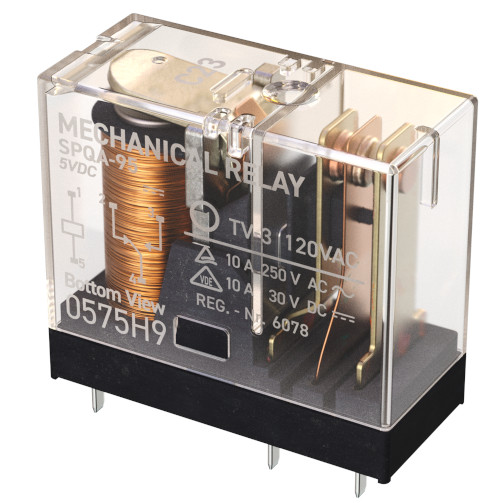
Figure 2. Electromechanical relay.
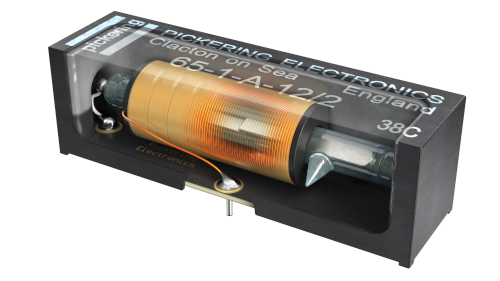
Figure 2b: High voltage reed relay
High-voltage reed relays have a switching speed of 0.5–1 milliseconds, much faster than EMR relays, which have a switching speed of 3 milliseconds. Finally, reed relays experience low mechanical wear because they contain no moving parts except for small commutating reeds. If used correctly and within specified parameters, reed relays can achieve a lifespan exceeding 1 billion operations (depending on the load). In contrast, EMR relays have a lifespan of only about 10 million operations.
There are, of course, many types of reed relays for high-voltage applications; generally, the higher the voltage, the larger the device. Reed relays with a breakdown voltage (DC or AC peak) of 1500V can be very compact, measuring, for example, only 12.5 x 3.7 x 6.6 mm. High-quality reed relays for these voltage levels incorporate powdered ruthenium contacts to deliver excellent performance at low current levels. Reed relays are characterized by breakover voltages up to 15kV. These larger devices have tungsten-coated contacts that offer resilience against the heat generated by high-power switching.
Several factors affect the relay's performance and lifespan. For optimal results, cold switching is always preferable, meaning activating the relay contacts without applying voltage. When hot switching is necessary, it is crucial to ensure that the product of the voltage and current at the switch does not exceed the relay's maximum specified switching power. Hot switching will negatively impact the relay's lifespan and reduce its breakover voltage, as electrical arcs are generated when the coating degrades. Therefore, switching module datasheets specify a reduced operating voltage of up to
40-50% when hot switching.
Even if no voltage is applied to the relay contacts, the switching may not be "cold." The main reason for failure in high-voltage relays is that the capacitance in the circuit is not properly assessed.
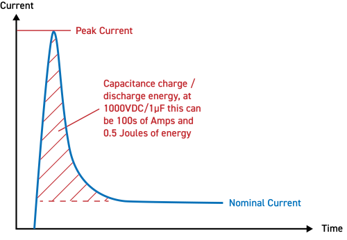
Figure 3. Transient capacitance in the switch and circuit diagram.
Let's look at Figure 3. If capacitance exists in the circuit, it can change when a high voltage is present. If the capacitance is in the switch without a limiting load, it will discharge instantaneously through the switch when it closes. Many high-voltage applications use capacitors to store voltages. Even capacitors charged to relatively low voltages can cause transient currents on the order of tens of amperes when the switch closes, which can significantly damage the relay contacts. Therefore, it is necessary to consider the nature of the capacitance in the circuit and include protection against discharges. This issue is discussed in detail in Pickering's Short Technical Guide to Reed Relays.
Manufacturers classify relays according to a certain performance level, but especially for components >10kV, it is not advisable to operate the device at its limits. When the device is new, its performance will be as specified, but over its service life, especially with hot-switching, electrical arcing and metal transfer between the contacts will occur. This can cause a buildup on a contact, thus reducing the contact gap, which in turn affects the breakdown voltage. If a margin of at least 10% is allowed in the operating specifications, the relay will operate reliably throughout its service life.
Another advantage of reed relays in high-voltage applications is their high insulation resistance and much lower leakage currents, on the order of nanoamperes, several orders of magnitude lower than those of solid-state relays (SSRs). The high leakage current of SSRs can make it difficult to measure current values on the order of milliamperes.
The connector is another critical component that requires special attention when evaluating switching products for high voltages. Type D connectors for high voltage, rated up to 1000V, are readily available and inexpensive. However, for applications above 1000V, special high-voltage connectors, such as those supplied by Redel, must be used. These Redel connectors are, contrary to what one might imagine, smaller than D-type connectors even though they can operate at higher voltages, and they use plastic insulation and lacquer inside the connector in order to provide the necessary insulation to handle extremely high voltages.
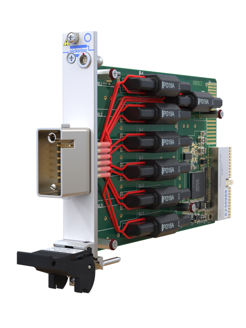
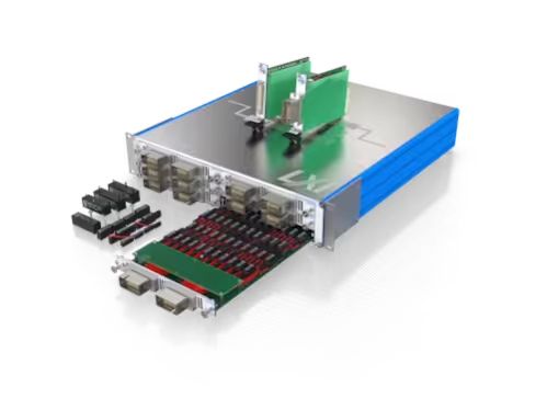
Figure 4. Pickering PXI switching module for 9kV
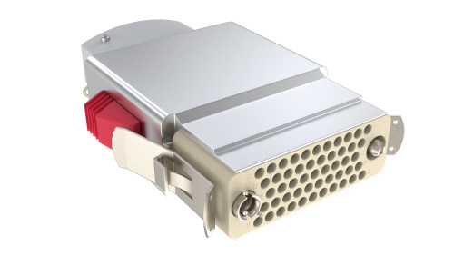
Figure 4b: Corresponding Redel high voltage connector (right).
Another significant factor in increasing reliability and minimizing the effects of spikes, transients, overcurrents, and overvoltages on modular switching boards is the use of surge suppression. For high voltages, two types of suppression circuits can be employed: one to protect the coil, which, if the relay is large enough, can be included in the relay housing, and additional suppression devices mounted on the LXI/PXI boards to protect the relay contacts from damage caused by spikes.
Repeatability:
Best practices help ensure that test results are accurate and repeatable. For example, it is essential to ensure that the load is as purely resistive as possible and does not include harmful capacitive or inductive elements. Both can damage the coating on the relay contacts and reduce their performance to the point of failure. Therefore, it is necessary to avoid surges, inductance generated by wiring, and stored capacitance, as these can lead to hot switching even when the board's power supply is disconnected.
Software errors must also be avoided. Automatic signal routing software can help manage the timing and routing of signals in switching systems, taking discharge time into account, thus preventing hard-to-detect sequential errors and potentially harmful signal connections.
There are, of course, other techniques to improve measurement performance. Reducing voltage levels to manageable levels using voltage dividers is a common practice in the industry, and signal conditioning methods can also be applied to more complex systems.
Abstract:
A thorough understanding of the factors influencing high-voltage switching has become crucial due to the exponential increase in demand, driven primarily by electric vehicles (EVs), but also by renewable energy systems and new generations of medical equipment, as well as more traditional high-voltage applications such as semiconductor, printed circuit board, and cable testing. Safety is always a top priority, and test system providers typically include hardware interlock functionality in their products. Reliability is ensured by using the most appropriate high-quality components and standard design processes. Repeatability can be achieved by following best practices in test programming. Breakdown voltage is a significant advantage of reed relay switching technology in high-voltage applications. Few applications switch at high voltages if they can avoid doing so, and if they do, it will be at low levels to protect the switch's lifespan. High breakdown voltage and low contact resistance make reed switches increasingly popular in applications where the primary function is current transmission, especially for current pulses. Using higher voltages can make it easier to generate currents that are unaffected by changes in circuit resistance and produce cleaner pulses, meaning a better pulse shape.