


On the other hand, all current sensors currently on the market introduce a phase error, which gradually increases in the high-frequency range due to delays in the electronic modules. This is compounded by design differences between models, which can alter the magnitude of this error.
A phase shift correction function allows you to compensate for this error. For the phase shift correction function to operate correctly, two things are required:
• a power analyzer that performs the correct calculations with its software
• a current sensor with a known phase shift.
To easily explain the calculations in the power analyzer software, it is helpful to compare it to the "deskew" or phase correction function on an oscilloscope. If two different signals are received on the oscilloscope at different times due to circuit latencies, the "deskew" function allows you to align these signals, thus compensating for their latency with a fixed time value.
In reality, entering a phase shift correction value in a power analyzer like the HIOKI PW6001 has the same effect, since a phase shift essentially consists of a delay between current and voltage. As an example, this figure shows what a delay looks like for a current sensor from the HIOKI CT68 series. The delay time is shown in nanoseconds as a function of frequency:
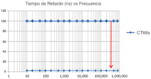 Figure 1: Time delay of the HIOKI CT68 sensor
A delay of 100 ns at a frequency of 100 Hz does not have the same impact as a delay of 100 ns at a
frequency of 1 MHz. This becomes clear when the aforementioned time delay is converted into a phase delay value expressed in degrees:
Figure 2: Phase delay as a function of frequency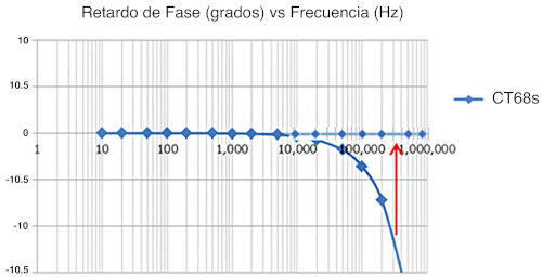
Naturally, this simple explanation requires that the time delay in the current sensor always be the same, regardless of the frequency. This is the case with HIOKI current sensors, such as the CT68 series, so, returning to the alignment function, one value is sufficient to compensate for the sensor's phase shift.
This is one of the attributes that distinguish HIOKI sensors, but it cannot be considered a standard property among current sensors available on the market. This is what can happen if a conventional current sensor is used:
 Figure 3: Comparison of conventional sensors with a HIOKI CT68 series sensor.
A sensor with a time delay that varies with frequency can significantly complicate phase shift compensation in a power analyzer. This is because it's unclear what value should be entered as the alignment or "deskew" parameter.
Another aspect that makes HIOKI current sensors unique is that the phase delay is independent of the conductor's position within the sensor during measurement:
 Figure 4: Phase delay of HIOKI CT68 sensors and cable position within the sensor
The reason only one line is visible on the graph is that the phase delay curves are identical for all five measurement positions. However, this cannot be considered a standard attribute of all sensors on the market. Typically, the position of the conductive core within the current sensor influences the values, as shown in the following graph:
Figure 5: Typical phase delay of the sensors and wire position within the sensor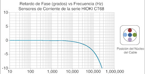
As you can see, phase shift compensation is not possible without a power analyzer that supports this function. However, it's also clear that the right combination of power analyzer and current sensor is essential for accurate phase shift compensation in measurements.
HIOKI has specialized in developing sensors for power measurements for many years, so the delay factor has always been a key focus for HIOKI engineers. In contrast, sensors from other manufacturers are typically designed for accurate DC current measurement, where the delay characteristic is less critical.
Therefore, combining HIOKI power analyzers with HIOKI current sensors is the ideal solution for a wide range of power analysis applications, from DC to high frequency. After all, it takes two to tango.