Battery capacity is measured in ampere-hours (Ah) and represents the maximum charge a battery can store. When its storage capacity falls below 80% of its initial capacity, it becomes hazardous waste and must be recycled. The main requirements for where the battery should be placed are as follows:
The floor must be in good condition to prevent any acid or lead spills from coming into contact with the ground. The roof must also be in good condition to prevent rain from entering. Avoid heat sources to prevent fires, and ensure the room is well-ventilated. The battery's lifespan at 25°C is 5 years, but it is typically around 2.5 years.
 A battery charger in a block diagram consists of four stages: a transformer, a thyristor bridge, an LC filter, and the battery as the load.
The transformer acts as a power adapter; the number of turns between the primary and secondary windings determines the power. It also converts the signal from three-phase to single-phase, if required. The rectifier bridge converts the signal to AC/DC, and the output power can be regulated by adjusting the thyristor angle. The LC filter filters the current and voltage signal with a ripple factor of ±1%, minimizing it to avoid intermittent operation. The battery serves as the load, and multiple batteries can be connected in series or parallel. Figure 1.
How to charge a battery?
To extend its lifespan, we must perform the correct charging and discharging process. There are three processes for charging a battery: charging, absorption, and float.
a) In the charging process, the battery's discharge level is never known, so a small current is gradually injected, increasing the voltage until it reaches the nominal voltage. Once the battery reaches 80-90% charge, it enters the absorption phase, where the current is rapidly reduced while the voltage remains stable. It is important not to exceed the maximum permissible charging current, as indicated by the manufacturer.
b) In the absorption phase, the voltage is controlled to maintain a constant level, and the charging current decreases slowly until the battery is fully charged. If the battery's voltage drops below 20% of its nominal current, it
is assumed to be over 90% charged and can proceed to the float phase.  c) The purpose of the float phase is to maintain the battery's charge level at 100%. In this process, the aim is for the current to compensate and prevent self-discharge, allowing the battery to remain at 100% charge.
The entire charging process takes between 4 and 6 hours, starting from an initial discharged state. Figure 2.
Charger control topologies.
The electronic charger takes a reading from the electrical grid every 100 Hz, that is, every two cycles, since the grid is rectified. In the circuit diagrams of these two battery chargers, slow charging is recommended to prevent battery overheating and thus extend its lifespan. In the first circuit, the charging current is controlled by the firing angle of the thyristors, according to the firing angle from the transformer's primary winding. The larger the angle, the greater the charging current to the battery.

 The power transformer adapts the input power to the output to achieve the correct power factor (cosϕ) and electrically isolate the charger. Figure 3.
The second diagram shows a fully controlled single-phase bridge with thyristors and an anti-reverse flyback diode; its performance is better than the previous diagram. Figure 4.
The control board must have good synchronization with the electrical grid to ensure proper firing. The charger functions as a voltage source, and the battery consumes the current necessary for the charging process.
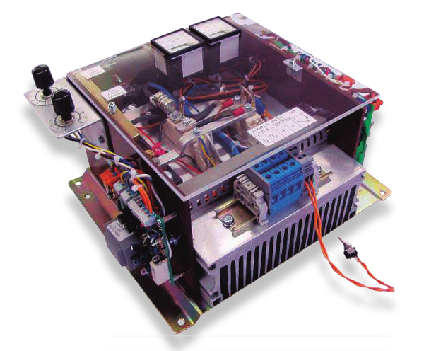
The photograph on the left shows the AC/DC power stage of a charger, consisting of a single-phase bridge fully controlled in voltage and current by two manual potentiometers that act as setpoint signals.
 Battery Charger Simulation:
We performed a simulation using the power electronics software POWERSIM. The circuit simulates a battery charger, showing the waveforms at different points. Figure 5.
The first graph shows the AC input voltage relative to the DC output. The second graph shows the waveform with a thyristor firing angle of α = 90° (the angle can
be α = 0° to 180°) and also the current through the LC filter inductance.
In the simulation, the LC filter has the following values: L = 5 mH and C = 400 µF.
Explanation of the charger with a three-phase circuit:
This converter is an electronic device that converts the alternating current (AC) signal from the mains to a stabilized direct current (DC) signal for charging a lead-acid battery.
The converter consists of a three-phase transformer and a bridge rectifier fully controlled by thyristors. This bridge regulates the output power using two reading points, configured with cascaded PID (proportional-integral-derivative) feedback, with the fastest possible response time and some filtering of the feedback signal. The first reading is current, taken by a current transformer. This current is controlled by the DC voltage reading via a stabilizing optocoupler, which then feeds the signal to the control board, triggering  the thyristors. The larger the firing angle, the more current is injected into the load (the battery).
The transformer is used to adjust the power levels so that the firing angle is as small as possible, minimizing signal distortion and ensuring good efficiency. The electrical grid is designed to minimize harmonics, resulting in a good power factor (cosϕ). A signal is sent to the control board, synchronizing and isolating it from the electrical grid to trigger the fully controlled bridge. The control board is designed to monitor the different battery charging stages: charging, absorption, and float. Figure 6.