

However, one of the challenges of solar energy is its intermittent nature. The sun doesn't always shine, and energy production can be irregular. Solar inverters require high efficiency and enhanced capabilities, and this is where integration with energy storage systems (ESS) becomes a powerful solution for ensuring a constant and reliable energy supply. As technology continues to improve and costs decrease, the adoption of solar energy systems with storage capabilities is expected to grow, paving the way for a more sustainable and resilient energy future. This article examines the advantages, types, and topologies for integrating energy storage with photovoltaic systems in residential and commercial installations.
Understanding how solar inverters and energy storage work
Solar inverters are the heart of a PV system. They convert the DC electricity generated by the solar panels into AC electricity that can then be fed into the grid. In addition to conversion, solar inverters manage the flow of energy, optimize system performance, and provide safety.
Energy storage systems (ESS) store energy for later use to help balance supply and demand and improve grid reliability. There are several types of ESS, such as:
- Battery energy storage systems (BESS), such as lithium-ion batteries, are used because of their high energy density, efficiency, and decreasing costs. They are common in grid storage and electric vehicles.
- Mechanical storage systems , such as pumped hydro storage, are the most established large-scale energy storage technology. They involve the movement of water between two reservoirs located at different elevations. This type offers the highest capacity form of energy storage.
- Thermal storage systems , such as " molten salt storage ," are used in solar thermal power plants to store heat and generate electricity when needed, especially in commercial applications for short-term storage.
In PV systems, lithium-ion BESSs are often used to store surplus solar electricity, ensuring a constant and reliable supply during periods of peak demand, at night and on cloudy days.
Advantages of integrating energy storage with solar inverters
Integrating energy storage systems (ESS) with solar inverters provides energy independence and reliability. By storing excess solar energy, users can reduce their reliance on the grid and ensure a constant supply even during outages or periods of low solar generation. This allows them to utilize stored solar energy during peak demand or when electricity prices are higher, reducing costs and minimizing strain on the electrical infrastructure. Furthermore, ESS can contribute to frequency regulation and optimize overall grid performance.
Segmentation of energy storage systems
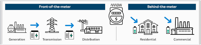
Energy storage systems (ESS) are divided into two segments: in-line (FTM) and behind-line (BTM). FTMs are typically associated with high-power systems above 5 MW, while BTMs are combined with residential and commercial photovoltaic systems ranging from a few kilowatts to 5 megawatts.
Types of solar inverters
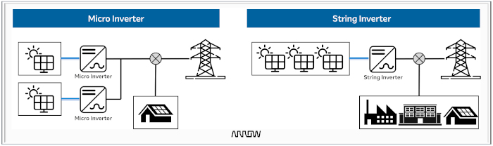
String inverters work by connecting solar panels in series, forming a chain. The combined DC power generated by the panels is sent to a single inverter, which converts it to AC. They are commonly used in residential, commercial, and utility installations. In the case of three-phase inverters, a panel voltage of 1000 to 1500 V DC is used with a boost converter. String inverters are cost-effective and easy to install and maintain. A problem can arise if one of the panels in the string is shaded or operating below capacity, as this can negatively impact the performance of the entire system.
In contrast, microinverters are designed to connect to each panel individually and convert the DC generated by each panel into AC. Unlike string inverters, which are connected in series, they are connected in parallel. Therefore, if one panel is shaded or operating below capacity, it does not affect the performance of the others. The typical power output of microinverters ranges from 200 W to 1.5 kW with a photovoltaic array voltage of 40 to 80 V. This type of inverter is ideal for residential systems where the panels can be oriented in different directions, as they maximize the production of each panel independently, mitigating the impact of shading or panel misalignment. The main disadvantage is the high initial cost.
Integrating energy storage (ESS) with photovoltaic solar panels results in a hybrid inverter. This type of inverter works in both directions: the generated DC energy is either converted directly to AC or stored before conversion. Hybrid inverters optimize energy use and storage by managing the flow of electricity between the panels, batteries, and the grid, allowing prioritization of battery charging, grid connection, or self-consumption.
Energy storage integration systems
There are two approaches to integrating ESS with PV systems: AC-coupled ESS and DC-coupled ESS. The fundamental distinction between an AC-coupled system and a DC-coupled system lies in the path the electricity takes once it is generated by the solar panels.
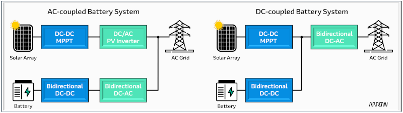
In an AC-coupled system, the PV system and the ESS are connected to the AC grid via their respective inverters. The solar panels generate DC, which a solar inverter converts to AC. The ESS, on the other hand, is typically equipped with its own bidirectional DC-DC converters and inverters for charging and discharging to the AC grid.
In contrast, in a DC-coupled system, the solar panels and storage battery share a DC bus and primarily use a single inverter to convert DC power to AC for grid or household use. The solar panels can be used to directly charge the batteries, and when needed, the stored DC power is converted to AC by a hybrid inverter.
|
AC coupled battery systems |
DC-coupled battery systems |
|
Advantages: - Flexibility: Battery systems can be easily installed in existing PV systems without making major changes to the current configuration. - Redundancy: Battery failures will not have a direct impact on PV power generation, and vice versa. - Modularity: Allows independent sizing of PV and storage systems. |
Advantages: - Greater efficiency: The DC-coupled configuration has fewer conversion stages than AC-coupled systems. - Cost-effective: Reducing the number of conversion steps allows for a more compact solution. - Optimized charging: Direct charging from the panels to the batteries can be more efficient. |
|
Disadvantages: - Loss of efficiency: There are additional conversion stages (DC to AC to DC), which can cause energy losses, between 5 and 10% more than in DC-coupled systems. - Complexity: More components and wiring, since AC coupling requires separate inverters for the battery and panels. |
Disadvantages: - High initial cost and complexity to add an ESS to an existing PV installation. DC-coupled systems are ideal for new installations. - Size limitations: The batteries must be very close to the inverter, which can independently limit the flexibility of the system. |
Power topologies for string inverters and ESS
Several power topologies can be used to design the DC-to-DC converter and DC-to-AC inverter stages. Different topologies offer distinct advantages and are chosen based on power, efficiency, cost, and complexity requirements. Here are some of the most common topologies:
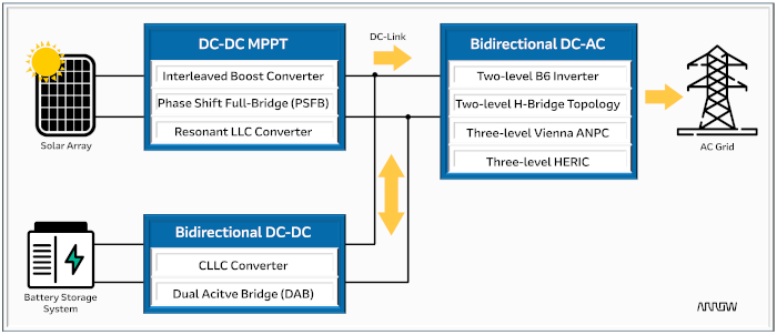
In the first stage of the converter, the maximum power point tracker (MPPT) is designed to maximize the energy production of a PV system by individually optimizing the performance of each solar panel in the array. It adjusts the panel's output current to its optimal power point before sending the energy to the inverter. This optimization is crucial, as the power output of a solar panel can vary due to changes in sunlight intensity, shading, temperature, and panel misalignment.
The current trend is to increase the DC link voltage to 1000 V or 1500 V to reduce energy losses in the system and allow for the addition of more panels in series. By increasing the maximum DC voltage of a solar inverter to 1500 V or higher, photovoltaic power plants become more cost-effective. Typical topologies for this stage include the interleaved booster, the full-bridge phase-shift keying (PSFB), and the LLC converter.
The second conversion stage consists of a bidirectional DC-DC converter. This stage is used to charge or store energy in the battery and discharge or release this energy when needed. Typical isolated topologies are CLLC and DAB.
The inverter's power stage converts the DC link voltage to AC voltage for the grid. Common topologies include the B6 and two-level H-bridge, as well as the three-level ANPC and HERIC. Multi-level inverter topologies have become popular in medium- and high-power applications. The advantages of using three-level inverter topologies are as follows:
- decrease in dissipated power, which translates into a smaller heat sink;
- voltage ripple reduction to make filtering easier due to lower harmonic content;
- significantly less conducted electromagnetic interference.
DC-DC topologies
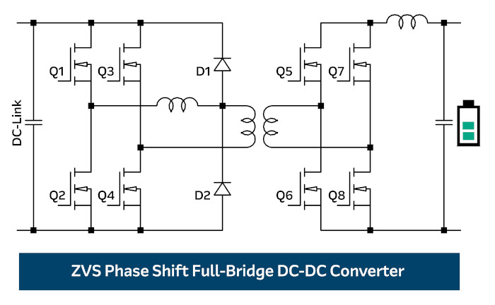
A zero-voltage switching (ZVS) PSFB topology is recommended in a 400 V DC link configuration using 650 V SiC MOSFETs for semiconductors Q1 to Q4 to achieve high efficiency and power density. The semiconductors are controlled using a phase-shift technique that allows them to turn on when the voltage across them is zero. This significantly reduces switching losses and electromagnetic interference (EMI), as well as the voltage stress on the semiconductor devices. Furthermore, 650 V SiC diodes are the correct choice for D1 and D2 on the primary side. For an 800 V DC link configuration, 1200 V SiC diodes and MOSFETs should be selected. On the secondary side of switches Q5 to Q8, the selection of the power switches depends on the battery voltage. For example, residential ESS systems typically use 48V batteries, while the commercial segment leans more towards 400V batteries.
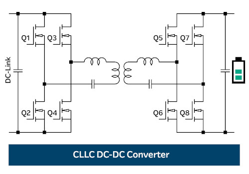
One of the most common bidirectional DC-DC converter topologies is the CLLC converter. It uses two inductors (L) and two capacitors (C) in a parallel resonant circuit. The arrangement typically resembles "LLC" reflected on both the primary and secondary sides. SiC MOSFETs are used for switches Q1 through Q4, while Si MOSFETs are selected for Q5 through Q8. The CLLC design achieves zero-current switching (ZC) of the semiconductors on the primary side, which helps reduce switching losses and improve efficiency. It can achieve zero-current switching (ZCS) on the secondary side to further improve efficiency by minimizing switching losses during turn-off. The CLLC converter requires precise control to effectively manage the resonant frequency and switching sequences.
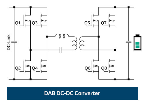
The DAB converter consists of two active full-bridge circuits on the primary and secondary sides, connected by a high-frequency transformer. Similar to the CLLC topology, both bridges have active switches that allow bidirectional power flow. Typically, SiC MOSFETs are used for switches Q1 to Q4, and Si MOSFETs for switches Q5 to Q8. The DAB converter requires advanced control algorithms to precisely manage the phase shift between the bridges.
Inverter topologies (DC-AC)
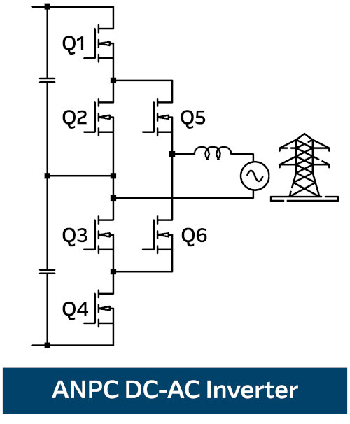
Active Fixed Neutral Point (ANPC) topology is an advanced inverter configuration. It builds upon the conventional fixed neutral point (NPC) topology by adding active switches that help reduce conduction and switching losses. The ANPC inverter can generate three voltage levels, reducing the voltage stress on each component and consequently achieving a more stable AC output with lower total harmonic distortion. Switches Q1 through Q4 operate at line frequency, while Q5 and Q6 modulate at 50 kHz or higher. In an ANPC inverter, all power switches can have a rated breakdown voltage of 600 or 650 V. Using SiC MOSFETs for switches Q5 and Q6 increases efficiency and power density. The ANPC inverter requires advanced control algorithms. This topology is more complex to design and control compared to topologies such as the H-bridge.
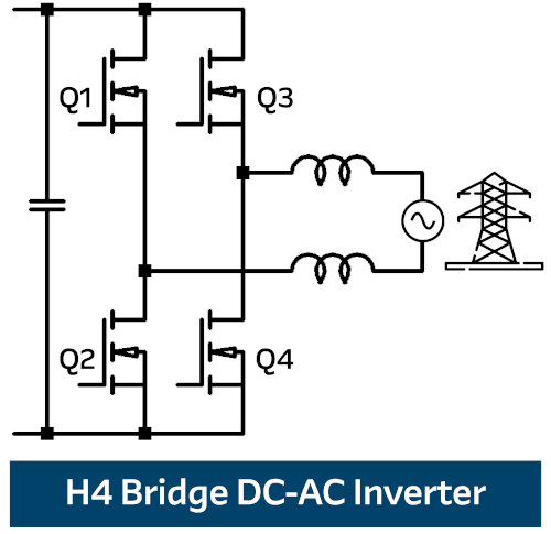
The H-bridge topology is popular due to its simplicity, efficiency, and versatility, as it consists of four switching elements. For the fast switching line, Q3 and Q4 typically use 650V SiC MOSFETs or GaN HEMTs, while for Q1 and Q2, Si MOSFETs with a fast body diode (SJ MOSFET) are the appropriate choice. The main drawback of this two-level operation is the use of a relatively large output filter, as it regenerates energy during the free-flowing current to the DC capacitor.
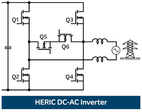
The Highly Efficient and Reliable Inverter Concept (HERIC) topology is particularly noteworthy for its high efficiency and superior DC-to-AC conversion performance. In this configuration, two antiparallel switches, Q5 and Q6, are added to the conventional H-bridge inverter to disconnect the AC side of the photovoltaic modules when no power generation is occurring. Six semiconductors comprise this topology, with the four in the H-bridge (Q1 to Q4) switching at high frequency and the two external ones at grid frequency. Semiconductors Q5 and Q6 allow current to flow along the shortest path during periods when the H-bridge inverter's output voltage is zero. The main advantage of the HERIC inverter is that only two switches operate simultaneously in all operating modes.
Wideband devices (WBG) are providing clear advantages to bidirectional DC-DC converter and DC-AC inverter topologies. SiC and GaN devices have very low switching energies and negligible or even zero reverse recovery charges (Qrr), reducing switching and reverse recovery losses.
Conclusion
Integrating energy storage with PV systems represents a significant advancement in how we harness and utilize solar energy. Providing a reliable and consistent power supply reduces grid dependence and maximizes the use of solar energy. These systems offer numerous economic and environmental benefits. SiC and GaN devices enable bidirectional flow for synchronous rectification topologies, achieving high efficiency and power density. Arrow Electronics has always championed energy efficiency, and we want to contribute to this discussion by demonstrating the clear advantages of choosing 650V, 1200V, and 2200V SiC devices with evaluation boards that simplify the design process and shorten time to market.
Omara Aziz - Global Power Technology Segment Leader, Arrow Electronics