


In this article, we will explore the advanced capabilities of the SLG47011V for measuring current, voltage, and power, highlighting the importance of leveraging its configurable logic and specialized features to meet the specific requirements of modern monitoring applications.
Current, Voltage, and Power Monitoring.
As one of the latest members of the GreenPAK family, the SLG47011 stands out for its integration of several key functional blocks:
■ A 14-bit SAR ADC capable of achieving speeds up to 2.35 Msps in 8-bit mode.
■ A programmable gain amplifier (PGA) that supports six amplifier configurations, with gain settings ranging from 1x to 64x, providing flexibility in analog signal processing.
■ An integrated 12-bit DAC, operating at sampling rates up to 333 ksps, enabling the accurate generation of analog output signals.
■ Another notable feature is the hardware math unit (MathCore), which supports multiplication, addition, subtraction, and division operations, facilitating efficient data processing without the need for external processors.
■ Integrated dynamic memory for 4096 words.
With these integrated blocks, the SLG47011V offers a versatile approach to monitoring current, voltage, power, and temperature. Using these internal blocks reduces the number of external components required. For example, the integrated PGA block eliminates the need for an external differential amplifier for current measurements. Furthermore, it offers additional advantages, as this configurable block allows for flexible adjustment of its parameters during the measurement process, including gain adjustment, which in turn increases the measurement range.
This combination of highly integrated analog and digital blocks in the SLG47011V significantly simplifies system design and enhances functionality. The ability to perform measurements and process data on a single chip not only reduces overall system complexity but also improves reliability by minimizing potential points of failure associated with using other external components. This level of integration, along with the flexibility of its programmable functions, makes it particularly well-suited for creating compact and efficient monitoring solutions.
The configurable nature of this device allows it to dynamically adapt to changing measurement requirements without the need for hardware modifications. This adaptability is especially valuable in applications where measurement conditions can vary significantly, enabling the system to maintain optimal performance across different operating scenarios.

Figure 1. Typical design for voltage, current, and power measurement
The design shown in Figure 1 is intended to interface with an MCU via I²C and can be conceptually divided into the following blocks:
Block A: Responsible for digitizing the incoming analog signals. It is worth noting that the programmable gain amplifier (PGA) can be reconfigured via I²C, allowing individual adjustment of the gain of each measurement channel based on the specific characteristics of the signals being measured.
Block B: Manages the ADC control logic, ensuring the correct startup of the ADC. The SLG47011V also offers offset compensation capabilities for differential measurements. This block monitors the timing and correct operation of the offset compensation during current measurement.
Block C: Handles the storage and processing of the digitized data. Buffers 0 to 3 store the digitized data (from the ADC) and act as filters, updating the data according to a moving average principle. The MathCore performs power calculations by multiplying the digital outputs of the voltage and current.
The results from each buffer can be read via I²C and subsequently displayed on the MCU or connected to a computer to establish a monitoring system.
The solution shown in Figure 2 allows the measurement of voltages up to 20 V and currents up to 4 A, provided that the PGA gain is changed via I²C according to the current: x32 for currents up to 1 A, x8 for currents from 1 A to 3 A, and x4 for 4 A.
Otherwise, this circuit can measure currents up to 1 A with a gain of x32. It is possible to reduce the gain to x16, thus increasing the maximum measured current to 2 A. However, since the initial design relies on overwriting the gain via I2C, it is important that the gain be overwritten for both channel 3 (which measures the current) and channel 2, as channel 2 calibrates the offset of channel 3.
The input voltage is applied to the +V_BUS pin and is designed for a voltage range of 4 V to 20 V.
Pins 7 and 8 must be connected together, as they are responsible for the offset calibration.
Pin 16 (Sync) serves as a signal pin that controls when the MCU can access the SLG47011. Communication with the chip via I2C is only possible when pin 16 is LOW.
R3 is a shunt resistor from which the current is measured.
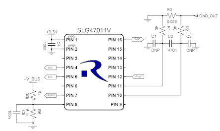
Figure 2. Typical application circuit
The data read by MathCore is converted using the following formula:
P=((2298537⋅M⋅2048))/(285212672000⋅G_e )
where:
M – data read by MathCore
Ge – channel gain
It is also possible to read the voltage and current values from buffers 0 and 3, which will be averaged in the same way as the buffer following MathCore. However, since there are two buffers connected in series for current, 16 bytes are averaged over 14 bits.
The voltage reading is converted using the following formula:
V_bus=((ADC_Vbus/2^N⋅Vref))/((R5/(R4+R5)))
where:
ADCVbus – data read by Buffer 1
N – resolution of the ADC
The current read is converted using the following formula:
I=(〖(ADC〗_SHUNT/2^N)⋅Vref/2)/((R3/G_e))
where:
ADCSHUNT – data read by Buffer 3
Functional Description of the Demo Board
: The SLG47011V Demo Board #1, which features an MCU for reading and displaying chip data, along with the components necessary for accurate measurements, provides a practical demonstration of the SLG47011V's voltage, current, and power measurement capabilities. Three boards were tested to determine the accuracy of the voltage and current measurements, and the results are described in section 3.1.
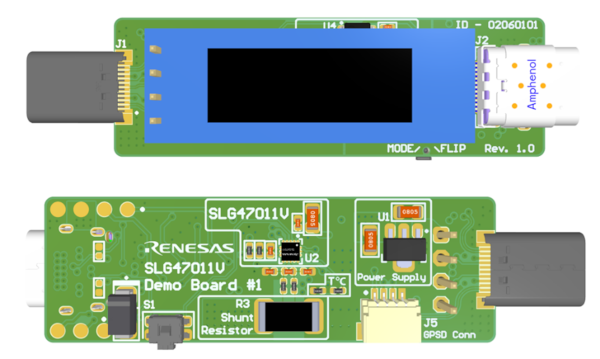
Figure 3. SLG47011V #1 Demo Board
Features
■ Compatible with power supply (up to 28 V, 5 A)
■ Measures voltage, current, power, and temperature
■ Measures in both directions (plug and receptacle connection)
■ 128 x 32 monochrome OLED display
Figure 4 shows a simplified functional diagram.

Figure 4. Functional block diagram of the SLG47011V demonstration board no. 1 R1.0
Measurement accuracy
Voltage and current measurements were performed on three different plates to collect statistics on accuracy (see Tables 1 and 2).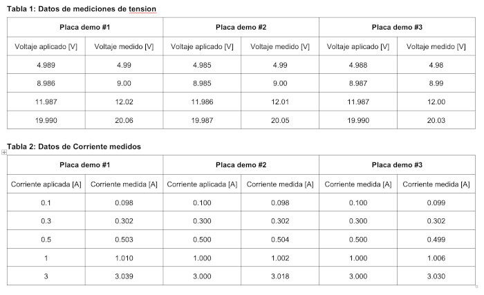
Customization Features
As mentioned previously, the SLG47011V is a configurable logic integrated circuit that allows for the implementation of advanced functions, such as watchdog timer functionality and overvoltage/overheating protection, among others, unlike other chips typically used in electrical parameter monitoring systems.
This enhanced design is used for the application note (AN-CM-375 Voltage, Current, Power, and Temperature Monitor).

Figure 5. Design with OVP, OCP, and OTP functions.
This configuration not only allows for simple measurements but also includes fault detection in the measured signals and outputs a fault signal externally when necessary.
Another feature is the ability to measure current in a copper chip (see AN-CM-394 Current Detection with Copper Trace).
In addition to the standard offset compensation available through the memory table and MathCore, it is also possible to measure current with the ability to compensate for temperature drift.
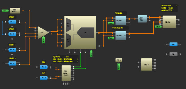
Figure 6. Design with temperature drift compensation.
Conclusion
In conclusion, the SLG47011V offers a flexible and efficient solution for current, voltage, and power measurement applications. Its configurable logic, along with features such as offset compensation, temperature drift correction, and fault detection, makes it a reliable choice for monitoring systems. The option to integrate additional functions, such as watchdog timers and overvoltage/overtemperature protection, increases its adaptability. With its programmability and high integration capability, the SLG47011V provides a practical platform for creating accurate, real-time monitoring solutions for a variety of applications.
Authors: Ruslan Tykhovetskyi, Application Engineer, Renesas Electronics, Lviv, Ukraine