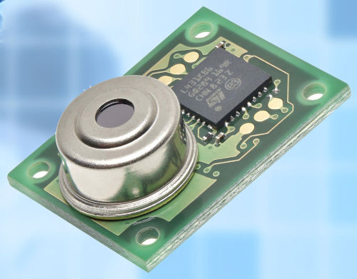



Panasonic PIR sensors (PaPIRs) detect infrared radiation at the same wavelength as that emitted by humans. With the help of a lens, the infrared rays are focused onto the individual elements of the sensor. The lens thus determines the arrangement of the detection zones, the field of view, and therefore the detection area and distance.
Sometimes, depending on the application and customer requirements, it is necessary to mask the sensor to limit the field of view. This application note shows how to do this and describes both a simple and a complex masking method.
The lens in Panasonic's PaPIR sensors is not a single lens, but a multi-lens system. This means that the sensing elements are projected in different directions by a variety of small lenses, as shown in Figure 1. In this application note, we will refer to the small lenses as "microlenses," while the complete lens will be called the lens.
 PaPIRs are quad sensors, meaning they use four sensing elements. As shown in Figures 1 and 2, each microlens creates a set of four radiation beams. It's important to know that it's not possible to isolate a single beam by partially covering a microlens; when a microlens is covered, all four beams are still present, but with reduced sensitivity depending on the degree of coverage. For example, when 80% of the lens area is covered, only 20% of the detection capability remains. Figures 2 and 3a illustrate this.
- Figure 2: Beam configuration for an objective with five microlenses. Because the sensor is a quad-element type, there are four beams in each of the five assemblies. It is not possible to separate a single beam within an assembly as shown in the top beam assembly (crossed out in red). In fact, if the lens is partially covered, the detection capability is reduced, as illustrated by the beam assembly at the bottom right.
- Figure 3a: Sensor without mask (top image) and resulting detection zones (bottom image).
- Figure 3b: Sensor with mask that completely covers the outer lenses (top image) and the resulting detection zones. The outer zones are completely covered (bottom image).
- Figure 3c: Sensor with mask that partially covers the outer lenses (top image) and the resulting detection zones. The detection zones are in the same position as without a mask, but their detection capacity is reduced (bottom image).
For proper masking, the desired operating conditions for each application must be carefully determined. For the mask itself, it is very important to choose a material that is not transparent to infrared rays.
 - Figure 4: Cross-section of the spherical mask and lens where the mask and lens share the same center point. The thickness of the mask is shown in red and the distance between the lens and the mask in orange.
The following example shows the lens of the PaPIRs HDLDDT, a 12m range sensor, used to observe movements in a 5m wide aisle, in a high-bay warehouse, with a sensor installation height of 8m.
The starting point is the unmasked detection zone of the HDLDDT sensor:
* Figure 5: Detection zones and field of view of the HDLDDT lens at an installation height of 8m. The red lines indicate the 5m wide corridor.
At this point, the customer must decide which beam sets to retain and/or which to completely mask. Two different methods or approaches for designing the mask are shown below.
Simple masking:
Conditions:
- Keep all beam sets
within the corridor completely covered (between the red lines in Figure 5, the
green beams in Figure 6)
- Create a spherical mask as shown in Figure 4
- Mask thickness: 1 mm
- Distance from lens to mask: 1 mm
The following concept was developed using SolidWorks:
- Figure 6: Since some microlenses are only partially masked, the detection capability is reduced. The loss of detection capability is proportional to the ratio of the masked lens area to the full lens area (70% of the masked area -> 70% loss of detection capability -> 30% detection capability). Note that this calculation must be performed in 3D to obtain the correct values. This can also be seen in Figure 4.
Complex masking:
Conditions:
- Completely maintain all beam sets
within the corridor (between the red lines in Figure 5, the
green beams in Figure 6)
- Completely cut off all beams outside the corridor
(outside the red lines in Figure 5)
- Mask thickness: 1 mm
- Distance from lens to mask: 1 mm
The following concept was developed using SolidWorks:
- Figure 7. Since there are no partially masked microlenses, the detection capability is either 100% or 0%.
The concepts shown in the previous example are for installation heights of 8 m. To calculate the detection zones at a different height, the intersection theorem can be used.
Panasonic is pleased to assist in creating masks tailored to various applications. To do so, please provide the following information:
- Lens type?
- Desired detection zones and installation height (e.g.
, 5m x 10m field at a 7m installation height
)?
- Which beamsets should remain unchanged?
- Which beamsets should be fully
masked?
- Mask design (spherical, flat, or other)?
- Distance between the mask and the sensor lens?
- Mask thickness?
@