

Introduction:
Understanding the operation of a Battery Management System (BMS) is essential when exploring ADI's BBU reference designs. The BMS is responsible for monitoring and regulating the battery's state of health, ensuring it operates within safe parameters. This includes monitoring battery cell voltages, temperatures, and overall current levels, as well as managing charge and discharge cycles. Implementing a robust BMS enables optimal efficiency and safety in system-level solutions. Ensuring a long battery life is crucial for achieving peak performance. Frequent, unintentional overcharging or over-discharging can damage the battery and shorten its lifespan. Carefully monitoring the battery's state of health (SOC) and using it properly will prevent unexpected downtime or failures and ensure optimal performance.
Furthermore, monitoring the battery's State of Charge (SOC) is important for the overall health of the battery pack. Over time, batteries lose capacity, and letting them drain to zero can accelerate this process. The optimal point for longevity is to keep the battery charged between 20% and 80%. Knowing the battery's SOC ensures that the battery unit module (BBU) continues to function for a longer period.
In addition to SOH and SOC, it's necessary to better understand the depth of discharge (DOD). DOD is an important factor to consider when using rechargeable batteries. It refers to the percentage of battery capacity consumed in a single discharge cycle. Generally, it's recommended to avoid discharging the battery below 20% DOD to prolong its lifespan. However, some batteries can withstand deeper discharges without significant damage. It's important to consult the manufacturer's guidelines for specific depth of discharge recommendations for a particular battery. Ensuring a long battery life is essential for achieving maximum performance. Frequent, unintentional overcharging or over-discharging can damage your battery and shorten its lifespan. Carefully monitoring your battery's state of charge (SOC) and using it properly will prevent unexpected downtime or breakdowns and ensure optimal performance.
Furthermore, monitoring the battery's State of Charge (SOC) is important for the overall health of the battery pack. Over time, batteries lose capacity, and letting them drain to zero can accelerate this process. The optimal point for longevity is to keep the battery charged between 20% and 80%. Knowing the battery's SOC ensures that the battery unit module (BBU) continues to function for a longer period.
In addition to SOH and SOC, it's necessary to better understand the depth of discharge (DOD). DOD is an important factor to consider when using rechargeable batteries. It refers to the percentage of battery capacity consumed in a single discharge cycle. Generally, it's recommended to avoid discharging the battery below 20% DOD to prolong its lifespan. However, some batteries can withstand deeper discharges without significant damage. It's important to consult the manufacturer's guidelines for specific depth of discharge recommendations for a particular battery.
Additionally, it's essential to carefully consider the battery's chemical composition. In the design of the BBU module, the use of lithium-ion (Li-ion) batteries was a prudent choice.
Factors such as manufacturing tolerances, variations in cell capacities, and differences in usage patterns can cause cell imbalances. These imbalances can lead to a reduction in overall battery capacity, decreased efficiency, and even premature battery failure. The design requires a passive balancer in the BBU. Passive balancing involves using resistors to purge or dissipate excess energy from cells with higher voltage levels. This method is relatively simple and cost-effective, but it can result in energy losses and heat generation. By ensuring that each cell in a battery pack operates at optimal levels, cell balancing improves the overall efficiency and effectiveness of energy storage systems, contributing to more sustainable and reliable operation of the BBU module system. The BMS microcontroller used in the BBU is the MAX32625. The BMS microcontroller is responsible for two important processes. See Figure 1.
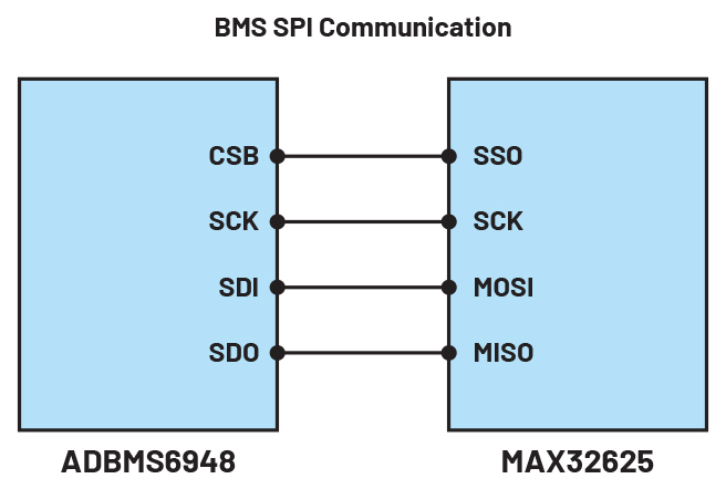
Figure 1. BMS Microcontroller A BMS microcontroller (MAX32625) connected to a BMS integrated circuit (ADBMS6948).
1. Communicate with the BMS IC (ADBMS6948) to obtain telemetry data for cell voltages, cell temperature, undervoltage, overvoltage, and overall battery stack current level.
2. Pass all telemetry data collected from the device to the main microcontroller via I2C communication.
The BMS microcontroller communicates with the ADBMS6948 using the SPI protocol. By sending the appropriate command codes, the BMS microcontroller allows the device to collect telemetry data and perform its operation simultaneously. See Figure 2. All data collected from the BMS IC will be sent to and processed by the BMS MCU.

Figure 2. BMS Microcontroller Process The BMS microcontroller process in the command and data storage of the BMS chip.
Another important task of the BMS microcontroller is to send the collected data to the main microcontroller for use in the charging and discharging algorithms, as well as in fan speed control. This is done via I2C communication with the BMS, which uses registers to be read by the main microcontroller. The register map for the BMS microcontroller is shown in Table 1.
Table 1. BMS Microcontroller Register Map
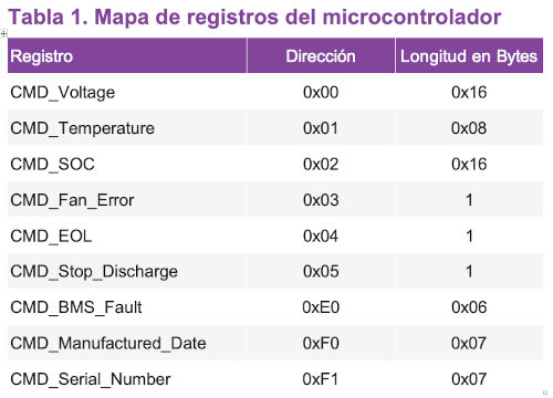
Please note that all BMS microcontroller registers are currently read-only. The manufacturing date and serial number are captured only once and stored in an external EEPROM of the main microcontroller.
Cell detection and balancing operation
Cell charging techniques
Constant voltage (CV) and constant current (CC) are two distinct charging techniques used in battery charging systems to optimize the charging process and improve battery life.
CV Charging
: CV charging is a charging method in which a fixed voltage is applied to the battery cell during the initial charging phase. When the charging process begins, the BBU module operates in charging mode and maintains a constant voltage level of 44 V, while allowing the 5 A charging current to gradually decrease as the battery's State of Charge (SOC) increases. This approach is particularly effective at preventing overcharging, as the voltage remains constant and does not exceed the battery's safe voltage limit. Once the battery cell voltage reaches 37 V to 40 V or a predefined threshold, the charger can switch to a different charging phase, such as reducing the charging current from 5 A to 0.5 A.
DC Charging:
DC charging, on the other hand, involves applying a constant charging current to the battery stack terminals. During this phase, the charging current remains constant at 5 A while the battery voltage gradually increases as it charges.
This method is especially useful for quickly charging a battery stack with low initial charge levels. It ensures a controlled flow of current into the battery stack until a specific voltage level is reached. Once the battery stack voltage reaches a predetermined point, the charging process can transition to a different phase, such as reducing the constant current from 5 A to 2 A or entering a constant voltage phase.
CV and CC charging methods are frequently combined in the BBU module's battery stack charging mode to achieve an optimal charging profile. The first CC phase helps to quickly supply energy to the battery, while the second CV phase prevents overcharging by restricting the voltage. This combined technique provides efficient charging, extends battery life, and maintains the safety and performance of the battery pack. The correct implementation of the CV and CC charging mechanisms is fundamental to the charging operation of the BBU module.
Cell Sensing Method:
The cell sensing method is a fundamental aspect of battery management systems. This technique is designed to accurately determine the voltage and condition of each individual cell in a battery pack. By employing sophisticated sensing circuitry and measurement algorithms, the cell sensing method allows the system to collect real-time data on the voltage, temperature, and overall condition of each cell. This information is then used to make informed decisions regarding charging, discharging, and balancing operations, thereby ensuring optimal battery performance, safety, and longevity. Effective cell sensing is critical to maintaining the overall efficiency and reliability of modern energy storage systems.
The 11 ADCs of the ADBMS6948 are dedicated to sensing the 11 differential cell inputs of the battery stack. The battery stack has an 11-cell series and 6-cell parallel configuration and is connected to pins C0 through C10, which are the BMS ADCs. They have an input range of -2.5 V to +5.5 V and a sampling frequency of approximately 4 MHz, producing 16-bit results every 1 ms with a 150 μV LSB. Eleven additional ADCs are dedicated to simultaneously measuring the 11 differential inputs using S-pins with an input range of 0 V to 5.5 V and a sampling frequency of approximately 4 MHz, producing 13-bit results with a 1.6 mV LSB every 8 ms. These S-ADCs enable redundant cell voltage measurement using a measurement approach completely independent of the C-ADCs.
Passive Balancing Operation
: Passive balancing is a technique commonly used in battery system management, in which the use of passive components, especially resistors, is combined with the integration of MOSFETs arranged in parallel with individual cells. These integrated components act as voltage purgers or energy dissipators, facilitating the controlled dissipation of excess energy from cells exhibiting high voltage or energy states.
The resulting gradual harmonization of the voltage potentials or energy states of the battery cells promotes voltage and energy balance over an extended period.
If the cells in a battery pack become unbalanced, the BMS must rebalance by discharging the cells with the highest voltage. The S-ADC pins of the ADBMS6948 can be used to discharge individual cells. The MOSFETs integrated into the S-ADC pins can be used for this purpose. Each S-ADC pin can be controlled individually or continuously using PWM. By configuring the PWMA, PWMB, and CFGB registers, it is also possible to balance the cells while the BMS microcontroller is in sleep mode.
Cell Charging with a Coulomb Counter:
The primary purpose of a coulomb counter is to accurately measure the amount of electrical charge (measured in coulombs) flowing into and out of a battery or circuit. This measurement allows for better control of battery bank charging and discharging, ensuring a longer battery bank life, greater efficiency, and more accurate capacity monitoring.
The ADBMS6948 has an integrated coulomb counter. This allows monitoring of the amount of charge flowing through the battery during the charging process. The coulomb counter, also known as an integrated current sensor or charge monitor, measures the total amount of electrical charge (in coulombs) transferred to or from a battery.
When charging a battery with a coulomb counter, the counter monitors the amount of charge delivered to the battery. This is done by measuring the current flowing through the battery and integrating it over time to calculate the total charge. Thus, by estimating the battery's State of Charge (SOC) and implementing charging algorithms, the charging process can be optimized.
The basic operation of an ADBMS6948 coulomb counter involves integrating the current flowing into or out of the battery cell over time to calculate the total charge transferred. Here's how it works:
► Current Measurement: The device measures the current entering or leaving the battery cell. This is typically done using a current sensor, such as a shunt resistor connected to the low side of the battery cell.
Integration: The measured current is integrated over time using the ADBMS6948. Integration involves summing the current values at regular intervals to calculate the accumulated charge.
► Capacity Calculation: The accumulated charge is converted into ampere-hours (Ah) or coulombs. This provides information about the remaining capacity of the battery bank.
► Monitoring and Display: The calculated capacity is processed, transferred to the main MCU, and displayed on the graphical user interface for further processing. This information is valuable for battery management, determining the State of Charge (SOC), and preventing overcharging or over-discharging.
During charging, the coulomb counter continuously measures the current flowing through the cell and integrates it over time. Knowing the battery's initial State of Charge (SOC), the SOC during charging can be estimated by adding the integrated charge to the initial value. This estimate helps prevent overcharging and allows for the implementation of charging algorithms that optimize the charging process for factors such as temperature, battery age, and chemistry.
See previous ADI articles for tips on balancing and optimizing battery life. These resources are highly recommended for those seeking more details on the subject. Kevin Scott and Sam Nork wrote two articles on cell balancing types: “Passive Battery Cell Balancing” and “Active Battery Cell Balancing.” For more details on cell characterization, please refer to “Characterizing a Li+ Cell for Use with a Fuel Gauge.”
Summary
Therefore, integrating ADI's ADBMS6948 BMS with a BBU is of paramount importance. A BMS offers numerous benefits that enhance the performance, safety, reliability, and longevity of the battery system. By optimizing battery performance, a good BMS helps maximize battery life and capacity, ensuring efficient use of its energy storage capabilities. It actively manages charging and discharging processes, preventing overcharging, over-discharging, and overheating that can damage the battery.
Safety is a critical aspect, especially in battery systems. A battery management system incorporates safety features and monitoring mechanisms to prevent thermal runaway and minimize potential risks. It protects against overcurrent, overvoltage, and abnormal temperature conditions, safeguarding the battery system and the surrounding environment. Energy efficiency is another major advantage of a BMS. Optimizing charging and discharging processes minimizes energy losses and improves the overall efficiency of the BBU. This translates into cost savings, a lower environmental impact, and greater use of available energy resources.
The BMS also monitors and accurately calculates the battery stack's State of Charge (SOC) and State of Health (SOH). This information is crucial for properly managing battery usage, calculating remaining runtime, and planning maintenance or replacement. The inclusion of a coulomb counter is important for precise measurement and control. This information is essential for efficient battery management and extending battery life in various applications, improving system reliability and reducing the possibility of unexpected failures.
Overall, the inclusion of ADI's ADBMS6948 BMS in the BBU plays a significant role in ensuring optimal data center performance, safety, and reliability. It provides critical information that every user needs to know to prolong its operation.
Part four of this series, "Smart Battery Backup for Uninterruptible Power Supply Part 4: How the BBU Shelf Works," will review how ADI designs and delivers a graphical user interface while enabling the user to communicate with and collect data from the six BBU modules in the BBU Shelf. It will also review the operation of the MAX32625, which serves as the dedicated MCU for the BBU Shelf.
The first part, already published, analyzes the electrical and mechanical design considerations of the BBU. The second part, also published, delves into the main microcontroller's software.
References
1 David Sun. "Open Rack/SpecsAndDesigns". Open Compute Project.
About the author:
Christian Cruz is an application development engineer at Analog Devices Philippines. He holds a degree in electronic engineering from the University of Oriente in Manila, Philippines. He has over 12 years of engineering experience in analog and digital design, firmware design, and power electronics, including the development of power management integrated circuits, as well as AC-to-DC and DC-to-DC power conversion. He joined ADI in 2020 and is currently supporting power management requirements for cloud-based computing and system communications applications.
About the author:
Marvin Neil Solis Cabueñas graduated with a Bachelor of Science in Electronic Engineering from De La Salle University in Manila, Philippines. Before joining Analog Devices in 2021, Marvin worked as a Systems Engineer for Azeus Systems Philippines, Inc. He then worked as a Network Engineer for Technistock, Philippines, Inc. from 2014 to 2017, and as a Research and Development Engineer for Nokia Technology Center Philippines from 2017 to 2020. He has over 10 years of work experience in various fields, including embedded systems programming, digital signal processing, simulation modeling, and others. He currently works as a Senior Software Systems Engineer on several energy-related technology projects. He is currently pursuing a Master of Science in Electrical Engineering at the University of the Philippines.