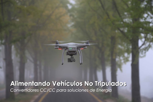

Figure 1: Examples of unmanned vehicles: delivery robot, multicopter UAV, underwater robot.
All these devices face common challenges. The most important is ensuring safe operation to avoid collisions with people or objects, or uncontrolled aerial accidents. The vehicles must be lightweight yet powerful enough to carry the heaviest possible payload and achieve extended operating times.
Although in many cases the payloads are quite small, each application may require different configurations of sensors, manipulators, or surveillance devices. Manufacturers can address this challenge by using flexible and modular platforms, as well as commercially available equipment, enabling rapid and cost-effective adoption based on specific needs.
How these unmanned vehicles are powered depends on the application and the required operating time. For short-range operations, batteries or supercapacitors are used; modern fuel cells allow for extended operation; and for long-range operations, combustion engines are used, or power is supplied via cable.
With all these parameters, powering the electronics of these vehicles becomes a key element for safety, expected operating times, and high payload capacity. Power source voltages vary, and many payloads require their own specific supply voltage. In this article, we will describe how P-DUKE power modules, part of Electronica OLFER's extensive product range, have enabled extremely flexible and modular power solutions.
The on-board architecture for these vehicles, whether aerial, land-based, or underwater, is very similar and consists of a power source, DC-DC converters for the various loads, speed controllers, and propulsion motors (Figure 2).
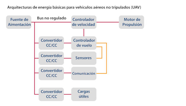
Figure 2: Basic power architectures for unmanned aerial vehicles (UAVs) - simplified block diagram
In most applications, the propulsion motor is powered directly from the power source to avoid additional conversion losses. In many cases, battery banks are used, and the required voltage and capacity depend on the system's size and maximum power. To avoid additional conversion losses, the motors are typically powered directly from the battery, while the rest of the system requires stable voltages.
For unmanned aerial vehicles (UAVs), 3.7V LiPo batteries are connected in series, with nominal voltages ranging from 3s = 11.1V to 16s = 59.2V (where "s" represents the number of cells in series). For longer flight times, fuel cells can be used.
Modern warehouse robots, whether autonomous (UAVs) or guided (UGVs), are equipped with Li-Ion or LiFePO4 batteries with nominal voltages ranging from approximately 24V for smaller systems to over 100V for heavy-duty applications such as forklifts.
What types of DC/DC converters are suitable for different power supplies in unmanned aerial vehicle (UAV) applications?
The wide range of power supply voltages presents a real challenge for designers seeking flexible and modular power solutions for use in diverse applications. P-DUKE and OLFER Electronics offer a comprehensive portfolio of DC/DC converters to meet these requirements, with input voltages ranging from 9V to 75V and 14V to 160V, single or dual outputs from 3.3V to 48V, and power ratings from 10W to 200W. These products are also rated for the harsh environments in which these vehicles sometimes operate.
To maximize payload capacity and space for cargo and safety equipment, all other components must be as lightweight and compact as possible. This is yet another reason to use highly efficient and compact DC/DC converters in the internal power chain. Efficiency has a significant impact on overall weight, as lower losses require smaller heat sinks. Using modules instead of a centralized power supply solution has the advantage that the converters and the dissipated heat can be distributed throughout the system, close to the loads, simplifying thermal management.
With P-DUKE's small and lightweight converters, it's easy to design a single solution suitable for different power supplies in various applications. What if another additional load voltage is needed? It's simple: just add another DC/DC module or replace one with a plug-and-play replacement from the same family, and you're all set!
Let's look at some examples:
• Smart and flexible factories: These factories require vehicles that navigate and transport goods autonomously within the production facility or warehouse. These vehicles use lasers and cameras for navigation and communicate directly with the manufacturing system and other robots. Autonomous vehicles can move almost freely, while guided vehicles (UGVs) follow a predefined route determined by visual markers, magnetic tapes, object recognition, and odometry data.
• Key challenge: Safe operation is paramount, as these powerful and heavy vehicles must detect human workers or other obstacles under all circumstances. This autonomous journey was made possible by significant improvements in camera, sensor, laser, and object recognition technology.
• Power architecture: Similar to Figure 1, the higher-power motors for lifting and moving the transported goods are typically powered directly from the battery. Wired or wireless solutions are used for charging the battery.
• Application example: In the application shown in Figure 3, the manufacturer's goal was to use batteries with nominal voltages of 24V or 48V, depending on the required power and desired load. For autonomous driving, the vehicle's onboard computer processes information from commercial cameras and LIDAR. Many industrial devices already have wider supply voltage ranges, but they do not cover 24V and 48V batteries. Here are some examples of different LIDAR systems with power levels ranging from 4W to 10W.
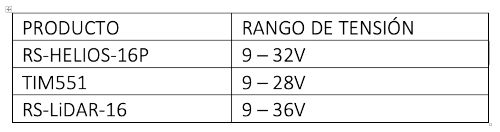
Therefore, a 12V bus was selected for the CPU, cameras, lidars, and other 12V equipment, and where necessary, small downstream converters generate 5V or 3.3V voltages. Isolated converters are used to prevent noise from coupling to sensitive sensors. See the HAE150W series (12V), the UDH03 and PDL12W series (5V), and the OSR03 series (3.3V) at www.olfer.com.
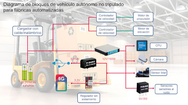
Figure 3 shows the block diagram of an unmanned autonomous vehicle (a driving robot for automated warehouses).
In low-power applications, where short, intermittent operating times and rapid recharging are possible, supercapacitors could be a viable option. Their energy density is lower, and newer technologies appear to be achieving values similar to those of a NiMH battery. Supercapacitors offer the advantage of containing no hazardous materials and having a much lower internal resistance, allowing for higher peak currents than batteries. Battery life is limited to 2,000–5,000 charge cycles, while supercapacitors can be charged over 1 million times without significant degradation. They also operate at very low temperatures, for example, in a food or frozen goods warehouse.
Unlike batteries, which maintain a nearly constant voltage during the discharge process, the voltage of supercapacitors drops significantly. The following example is for a small robot with a total power consumption of 100W and a maximum operating time of 60 seconds between charge cycles.
Energy calculation:
E = P * t = 100W * 60s = 6kJ = 1.67Wh
Maximum capacitor bank voltage: 48V Minimum voltage: 12V
Required capacity:

By connecting seventeen 3V/100F supercapacitors in series, the required capacitance can be achieved at a maximum nominal voltage of 51V.
Figure 4 shows the discharge curve of this supercapacitor solution compared to a standard 48V battery.

Figure 4 shows the discharge curves of supercapacitors versus batteries.
Although supercapacitors are certainly more expensive than batteries, the supercapacitor bank can be recharged during operation in a matter of seconds, allowing the robot to run 24 hours a day without interruption. Considering the difference in lifespan and the cost of replacing faulty batteries, the supercapacitor solution is more economical in the long run.
To cover the wide voltage range of capacitors (from 12V to 48V), a converter is needed. No problem! P-DUKE offers a converter with a 9V to 75V input and a 100W output. See the QAE100U series.

Figure 5: Typical power architecture of a robot using a supercapacitor power solution.
The final example is a small unmanned helicopter system with a flight time of over four hours, requiring a fuel-powered engine. Unlike what is shown in Figure 1, the rotors are directly driven by the engine, which also provides the typical 28V aircraft voltage for the flight control systems. The helicopter may be equipped with infrared/optical gimbals, various sensors, lidar, 3D mapping and geolocation systems, and many other devices that require a stable 12V supply with a total power of 170W.
The necessary 28V to 12V DC/DC converter must be lightweight, capable of operating in ambient temperatures as low as -40°C, and withstand the high stress of shocks and vibrations from the rotors. IP67 protection and complete shielding against electromagnetic interference (EMI) necessitated a hermetically sealed chassis for all the electronics and, therefore, conduction cooling for the power converter.
The ideal solution was the P-DUKE HAE200W half-enclosure inverter (Figure 6). It operates within an input range of 16.5 to 75V, even at ambient temperatures as low as -40°C, and its metal base allows for conduction cooling of the helicopter's airframe. Thanks to its silicone encapsulation, it meets the shock and vibration requirements specified by MIL standards. Weighing only 105g, this inverter represents less than 0.5% of the helicopter's total weight. Furthermore, with a maximum power output of 212W, it also provides ample headroom for additional loads or peak loads.

Figure 6: Simplified power chain of the unmanned helicopter system.
The remote control unit can be powered from a 12V battery or from the 28V MIL mains (16V to 50V range) of a boat or land vehicle. The RF amplifier requires a powerful 28V source, so this voltage was selected as the main bus voltage. A 100W converter from P-DUKE's QAE100U family, with an input range of 9V to 75V, generates this 28V bus, and downstream, lower-power P-DUKE converters provide the necessary supply voltages within the remote control unit (Figure 7).
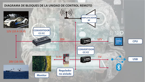
Figure 7: Block diagram of the remote control unit.
Each UAV application can present different challenges and requirements. In this article, we want to focus on some key elements of the power supply chain that, in most cases, share common requirements: small footprint, low weight, high efficiency and reliability, but even more importantly, flexibility, modularity, and ease of use.
Ultimately, designers need a competent partner that offers the necessary product portfolio and can help the customer find the optimal solution for their specific requirements. P-DUKE and OLFER Electronics can help.
Author: P-DUKE Marketing Department.
Translation: OLFER Electronics Marketing Department.