This article investigates the basic concepts of power conversion and presents the most commonly used topologies for discrete and modular designs. The article also addresses fundamental aspects of isolation and voltage regulation.
Power conversion is everywhere.
You'll find power conversion applications in almost all the technology you use. Take your mobile phone, for example. It most likely has a lithium battery with a nominal output voltage of 3.7V. The phone's numerous ICs and associated applications may operate at different voltage levels, the most common being 1.8V, 3.3V, or 5.0V. Power conversion applications take the 3.7V and transform it into the appropriate voltage level, either above or below the battery's nominal output voltage.
Another similar example is the simple but popular portable USB charger that helps us recharge our tech devices anywhere. This also uses a single lithium pouch battery cell that supplies 3.7V and a DC/DC converter that boosts the output to provide the standard 5V USB output.
Your speaker, TV, laptop, and smart appliances all convert the power supply voltage to the appropriate level for their internal circuitry.
AC/DC and DC/DC conversion methods include two distinct techniques: linear and switching. The linear method was commonly used in equipment powered from the electrical grid, but it required bulky components such as transformers and large smoothing capacitors. Linear regulators are still used in some specialized DC/DC conversion tasks, but today, most applications employ a switching regulator method.
The switching DC/DC conversion method is based on storing energy in an inductor or capacitor. Unlike the linear method, the output voltage provided by a switching regulator can be higher or lower than the input voltage. Figure 1 illustrates the basic concept of a switching DC/DC converter.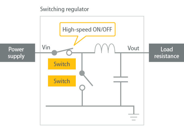 Figure 1: Functional block diagram of a DC/DC converter (source: Murata)
A PWM signal is applied to a semiconductor device as a switching drive. The duty cycle (the mark-to-space ratio) and frequency of the PWM input directly affect the conversion efficiency, load regulation, and output voltage. Essentially, the PWM and the switching semiconductor create a charge pump circuit to store energy in an inductor or capacitor during the ON cycle. This energy is released and rectified during the OFF period of the PWM signal. Output voltage regulation is applied to the PWM signal. Isolation from input to output is achieved using a transformer—as an inductive element—and a capacitor.
Over the years, several DC/DC converter architectures or topologies have become popular, which we will briefly explain.
The most common DC/DC converter topologies
The buck converter (or step-down converter)
An asynchronous buck converter topology converts an input voltage to a lower output voltage (for example, 5VDC to 3.3VDC). Figure 2 shows a simple explanation of the circuit.
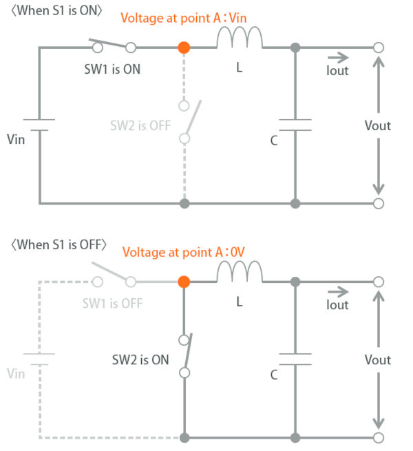 Image 2: The main function of a step-down converter (source: Murata)
In Figure 2, SW1 is typically a transistor driven by a PWM signal, and SW2 is a diode. When SW1 is closed or ON, current flows through the inductor and energy is stored. When SW1 is OFF, energy is released as current flows through the diode, represented by SW2, supplying an output voltage.
The output voltage of the buck converter depends on the duty cycle of the switching PWM signal, as shown in Figure 3.
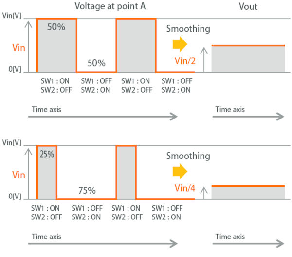 Figure 3: The effect of the duty cycle on the output voltage (source: Murata)
In a synchronous buck converter topology, the diode is replaced by another switching element, typically a FET. It is driven by an out-of-phase switching signal. FETs generally offer lower forward bias resistance, which reduces losses.
The boost converter (or step-up converter):
As its name suggests, in a boost converter the output voltage is higher than the input voltage. The degree of increase depends on several factors, but for most practical applications, the maximum is up to five times the input voltage. A value of up to three times is more feasible for proper output voltage regulation. See Figure 4. 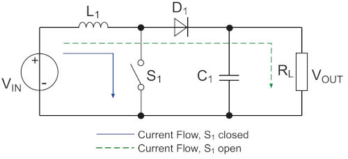
Figure 4: The basic concept of a boost converter (source: Murata).
Compared to the buck converter arrangement in Figure 2, the switching transistor S1, inductor L1, and diode D1 (which was a switch in Figure 1) are placed in slightly different positions. When S1 is ON, energy is stored in L1, and when it is OFF, energy is added to the input voltage flowing through the input capacitor and then to the output capacitor.
Boost and buck converters use very few components, and this method allows them to achieve high energy efficiency, typically up to 97%.
Neither buck nor boost converter topologies are isolated. This means that any input voltage can appear at the output. If the DC/DC converter is powered by an AC source, a fault could cause the AC line voltage to appear at the output, with potentially fatal consequences. Many applications require galvanic isolation between the input and output, such as medical and healthcare applications. For example, one way to achieve galvanic isolation in a switching regulator when the ground connection is not common is to use a transformer. An example of this is the isolated reverse converter (see Figure 5).
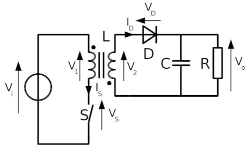 Image 5: Simplified schematic of an isolated reverse converter (source: Wikipedia)
The isolated reverse converter
In an isolated reverse converter, the transformer is the energy storage inductor while also providing isolation. This topology is perhaps the simplest of all DC/DC converters, as it has few components. Applications are typically limited to low-power applications (
Push-pull, half-bridge, and full-bridge converters
are examples of other isolated switching topologies currently in use. The push-pull arrangement uses two switching devices that share the current and is suitable for high-power applications. This topology uses center-tapped split primary and secondary windings, which requires a more expensive transformer. Half-bridge and full-bridge topologies are similar to push-pull but require only one primary winding. The half-bridge uses two switching devices, and the full-bridge uses four. (See Figure 6.)
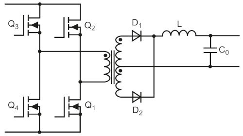
Figure 6: Simplified schematic of an isolated full-bridge DC/DC converter
Output Regulation:
In addition to basing the design of a DC/DC converter on a specific topology, deciding how to regulate the output voltage is also an important issue. Accurately regulating the output under any load condition is especially important for processors with rapidly changing, dynamic workloads. The output voltage must be returned to the PWM switching function quickly and accurately to enable duty cycle changes. Today, most DC/DC converter control ICs include this function, which is easily achieved in a non-isolated topology.
However, maintaining isolation from input to output requires additional components, increasing the bill of materials cost. Common isolated feedback methods include using an additional transformer or an optocoupler. The need for additional components not only increases the bill of materials cost but also the printed circuit board space requirements. And in today's space-constrained designs, printed circuit board space must be minimized. In addition to considering the cost of the bill of materials, it's important to remember that the more components used in a design, the more complex the logistical and component supply challenges become. Using a larger number of components will also negatively impact the reliability of the final product.
DC/DC Converter ICs and Modules:
A recent innovative solution uses primary-side sensing to provide a much simpler regulation method. During the "OFF" phase of the flyback, the driver IC senses the secondary output reflected through the transformer. An example of an "opto-free" flyback driver IC is the Maxim MAX17687: see Figure 7.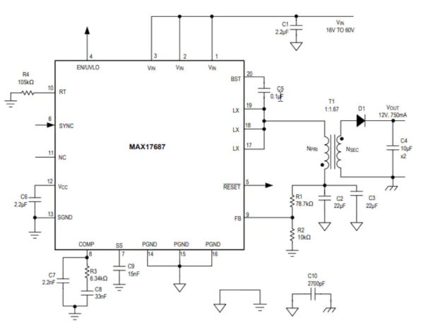 Figure 7: Example of an opto-free flyback converter IC with a minimal number of components to create a 12V/750mA output from a 16A 60V source. The Maxim MAX17687 (source: Maxim)
The MAX17687 driver includes two on-chip MOSFETs capable of driving a maximum primary current of 3.2A. Employing primary-side sensing, the output voltage is regulated within a range of +/-1.2%. The IC's PWM frequency can be programmed between 100 and 500kHz, and the conversion efficiency is typically greater than 90%.
An example of a complete DC/DC reverse converter module is the Murata UWS-Q12 series, an open-frame, insulated module assembled using through-hole technology.
These modules offer an attractive alternative to discrete DC/DC converter designs. Firstly, they significantly simplify the design development process, potentially leading to substantial reductions in engineering time. They are also beneficial from a bill of materials perspective, reducing the number of components and simplifying logistics. Another aspect to consider is that the modules are usually already certified in accordance with EMC/EMI regulations and health and safety standards, which further simplifies product approval.
The compact UWS-Q12 series, with 91% efficiency, offers the usual single-output nominal voltages of 3.3, 5, 12, 15, or 24V and can deliver up to 54 watts from an input voltage of between 9 and 36V. It includes a comprehensive set of self-protection features, such as protection against low input voltage and over-temperature. 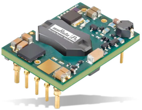 Image 8: The Murata UWS-Q12 (source: Murata)
The Traco TSR 1.5E series is a practical replacement for inefficient, older linear regulators. This 1.5A plug-and-play device utilizes a non-isolated buck (or step-down) topology to achieve up to 97% efficiency and accommodates a wide range of input voltages. The devices in this series provide 3.3V DC (replaces part number 7803), 5V DC (replaces part number 7805), and 12V DC (replaces part number 7812).
TI has adapted the buck converter topology with its DCS (Direct Control Smooth Transition) control technology. The modified DCS topology achieves significantly better transient response, regulation, and ripple characteristics than a synchronous buck converter. TI supplies the converter as a driver IC, the TPS6282x, and as a converter module with an integrated inductor. Figure 9 shows the functional block diagram of the non-isolated buck converter module with the integrated FETs and inductor.
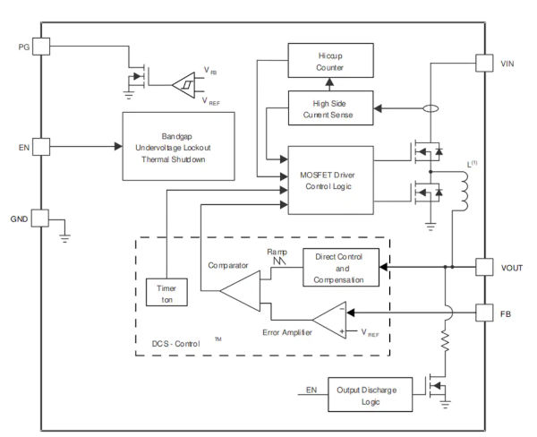
Figure 9: Functional block diagram of the TI TPSM82821 buck (or step-down) converter module with the TPS6282x controller IC (source: TI)
Simplified Energy Conversion:
In this article, we have investigated some of the most common DC/DC energy conversion topologies and highlighted a few example products. Converter ICs are a widespread method for DC/DC conversion that is efficient in terms of space and bill of materials. Low-power converter ICs that integrate switching transistors or FETs are extremely popular in many industrial, commercial, and consumer products. DC/DC converter modules that incorporate the driver IC, inductor, and all additional components are the easiest to integrate into a final product and readily available.
Author: Mark Patrick, Mouser Electronics
www.mouser.com