

Traditional DC/DC and DC/AC inverters and converters are proving inadequate or inefficient for the most critical and challenging applications, such as next-generation satellites, drones, and electric aircraft. High-density power modules have proven to be an effective solution for overcoming these challenges and achieving high levels of reliability, power density, and flexibility.
An unprecedented boost to all aerospace power applications is coming from the third generation of wide-bandgap (WBG) semiconductors. Silicon carbide (SiC) is ushering in a new era of aerospace power supplies, characterized by more efficient, smaller, and lighter power solutions.
Properties of SiC:
While the properties of SiC have been known since the late 19th century, this WBG material has only recently been used as a semiconductor. Compared to traditional silicon-based power devices, SiC MOSFETs exhibit a high breakdown electric field (3–5 MV/cm, almost 10 times greater than that of silicon) and a band gap approximately three times larger than that of silicon (3.26 eV vs. 1.11 eV). Furthermore, thermal management is improved thanks to SiC's thermal conductivity, which is about three times greater than that of silicon (4.9 W/cmK vs. 1.5 W/cmK), while its specific resistance is much lower than that of silicon (0.3 mΩ/cm² vs. 400 mΩ/cm² for a breakdown voltage of 1200V at room temperature). The on-resistance (RDS(on)) of commercially available SiC power devices can be 300 to 400 times lower than that of an equivalent silicon device with the same breakdown voltage.
Compared to their silicon counterparts, silicon MOSFETs can operate at higher switching frequencies with lower conduction and power losses, allowing for smaller passive components in power supply systems and more compact and lightweight power solutions. This, in turn, has enabled the replacement of existing IGBT devices with SiC MOSFETs in space-constrained, high-power applications, such as in aerospace.
SiC Applications in the Aerospace Sector:
The gate driver circuit for SiC MOSFETs requires a high positive gate voltage (around 20V) and, depending on the application, a negative gate-off voltage of −2V to −6V (for dV/dt immunity and to achieve the fastest turn-off speed). Along with low output capacitance and low RDS(on), this makes SiC devices attractive for switching designs such as power supplies, three-phase inverters, amplifiers, and voltage converters (AC/DC and DC/DC). The use of SiC devices also significantly reduces the cost and size of magnetic components (transformers and inductors) used in many aerospace power applications.
The More Electric Aircraft (MEA) concept has become very popular in the aerospace industry, aiming to electrify auxiliary aircraft systems that were previously powered by mechanical, hydraulic, and pneumatic means. The MEA approach offers significant advantages such as improved efficiency, reduced costs, and increased reliability.
As a result, new power devices are being designed to meet MEA requirements, as is the case with AC/DC power systems that require electronic converters for operation.
Several power conversion functions required by an MEA power system are performed by DC/AC converters, such as engine starting, pump and generator control, and flight control actuators. To meet such demanding requirements, DC/AC converters with high power density and the ability to achieve high switching frequencies are needed. Efficiency is also a key factor, as it allows for a reduction in the size and weight of the converter, thus simplifying thermal management. Due to their low conduction and switching losses, SiC power devices are emerging as viable candidates to replace silicon-based IGBTs and MOSFETs in aircraft power converters.
Towards Clean and Sustainable Aviation:
The entire aerospace industry is aiming for zero emissions, which is why it is developing new technologies capable of emitting fewer greenhouse gases and promoting the use of other sustainable fuels.
In Europe, the Clean Sky Consortium, an alliance between the European Commission and the European aerospace industry, aims to develop cleaner air transport technologies capable of reducing CO2, NOx, and noise emissions. IATA (International Air Transport Association) is leading a similar initiative and last October approved a resolution for the global air transport sector to achieve net-zero carbon emissions by 2050.
To meet these demanding requirements, pneumatic and hydraulic control systems must be gradually replaced by high-efficiency electric and electrical control systems. Greater efficiency is a key factor in reducing fuel consumption, weight, and size.
Microchip
Technology recently introduced a series of small-profile, lightweight AC/DC and DC/DC power modules that deliver higher power conversion efficiency through the use of SiC. The BL1, BL2, and BL3 families, capable of delivering power from 100 W to 20 kW, were developed in collaboration with the European Clean Sky Consortium to meet the aviation industry's increasingly stringent cleanliness requirements. This includes compliance with the RTCA DO-160G test procedure ("Environmental Conditions and Test Procedures for Aircraft Equipment, Version G"). A DO-160G compliant device can operate reliably and accurately under all flight conditions.
The new power modules (Figure 1) feature a modified structure that reduces weight by 40% and costs by 10% compared to conventional solutions that incorporate metal base plates and require a heat sink. Furthermore, its low-inductance, low-profile package can be soldered directly onto the printed circuit board, which accelerates development and increases reliability.
 Figure 1: Low-profile, low-weight BL3 power module.
This family of devices, the first low-profile, low-weight power modules certified for aerospace applications, consists of three sizes of power modules (BL1, BL2, and BL3). The standard configuration integrates all-SiC 1.2 kV topologies with or without freewheeling diodes. These modules are supplied as 75 A and 145 A SiC MOSFETs, 50 A IGBTs, and 90 A rectifier diode outputs. Custom IGBT-based solutions containing devices for voltages from 700 V to 1700 V are also available. Depending on the version, they support different topologies, such as full bridge, asymmetric bridge, phase branch, dual common source, buck, and boost.
Figure 2 shows the phase branch topology supported by the BL1 power module (1200 V, 79 A, typical RDS(on) 25 mΩ). The SiC power MOSFET stands out for its low RDS(on) and high switching frequency, while the SiC Schottky diode provides zero reverse and forward recovery and temperature-independent switching.
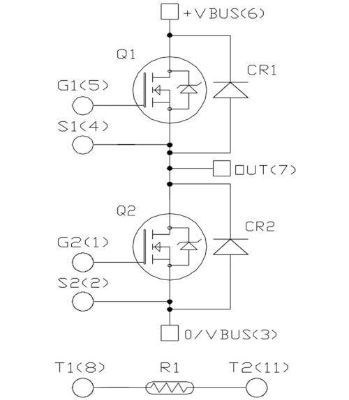 Figure 2: Phase branch topology supported by the BL1 power module.
The BL2 and BL3 power modules support the full-bridge topology shown in Figure 3. These modules are characterized by a drain-source voltage of 1.2 kV, a continuous drain current of up to 150 A at room temperature (up to 300 A pulsed drain current), and a drain-source on-resistance starting at 16 mΩ. The SiC MOSFET incorporates a Kelvin source for easy control, and the SiC Schottky diodes also offer zero reverse and forward recovery. The maximum power is 560 W, while the maximum gate-source voltage is -10 V (off) and 24 V (on).
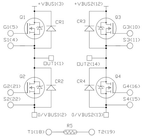 Figure 3: Full-bridge topology (dual-phase branch) available in the BL2 and BL3 modules.
Validation Testing:
All BL1, BL2, and BL3 power modules have undergone validation testing by Microchip to demonstrate their suitability for aerospace applications, meeting the required levels of reliability, performance, and efficiency. The test procedure, based on RTCA DO-160G and compliant with civil aviation environmental conditions, included parametric testing across the entire voltage, current, and temperature range (-55°C, 25°C, and 125°C), partial discharge testing (10 pC max. at 1200 V AC), high-potential testing (3 kV AC), and insulation resistance testing (>100 MR at 500 V DC).
These tests were performed by Microchip Technology:
• High-temperature gate bias testing. The purpose of this test, performed at VGS = 20 V and
VGS = –8 V, is to verify that the device's performance is not affected by high-temperature gate bias. At a junction temperature of 175°C, Vth measurements before and after 1000 hours of high-temperature gate bias show negligible variations.
• Temperature cycling. The objective of this test is to evaluate the device's resistance to extreme temperatures, both high and low. X-ray and scanning electron microscopy analysis, performed after 1000 cycles (see Figure 4), shows no degradation at the solder joint or substrate level that could affect the device's performance.
• Vibration and shock. After attaching the power modules to a board mounted to a vibration generator, the level of vibration and shock was checked on all three axes.
• Chopper-mode bias (CMB). The purpose of this test is to verify the robustness of the device when operating in chopper mode at high temperature. The test conditions were as follows: VGS = –5 V, switching frequency = 20 kHz, duty cycle = 0.5, T = 150°C, test duration = 1000 hours. Figure 5 shows the CMB test graph after 1000 hours (200 V/div).
• Partial discharge. This test aims to verify the insulation condition of the test device and is important for SiC power modules, which operate at high voltages and high dV/dt.
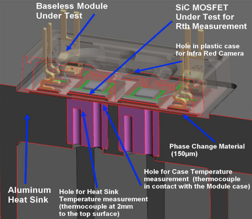
• Thermal simulations and measurements. The thermal simulation determines the thermal resistance and thermal impedance values of the test device, while the thermal measurement confirms the thermal resistance between the junction and the heat sink calculated during the simulation. The test switch, previously prepared with a modified encapsulation (see Figure 6), was activated, and a constant current generator caused a rise in junction temperature to calculate the thermal resistance. The measurement results confirmed the thermal simulations.
 Figure 4: X-ray analysis before and after 1000 temperature cycles.
 Figure 5: Graph of the CMB test.
 Figure6: Configuration for thermal measurements.
All tests performed by Microchip were passed, thus demonstrating the reliability of the low-profile, low-weight power modules, as well as the suitability of this technology for the most demanding applications in aircraft.
Author: Alain Calmels, Design Engineer, Microchip Technology