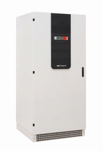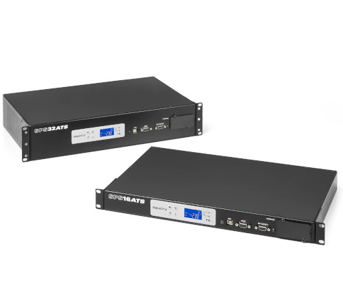



The product standard for UPS systems (EN62040) defines different types of UPS, among which the VFI ("on-line," double conversion) type stands out. This type is characterized by generating an output waveform for the load with voltage and frequency independent of the primary grid. From a qualitative standpoint, this type of UPS offers the best performance because it isolates the load from all types of grid disturbances. It generates a new waveform by first converting the primary source voltage to DC and then regenerating a completely disturbance-free waveform for critical loads. However, while this topology offers the highest quality, it is the least efficient because energy flows through two converters in series at full power, resulting in accumulated energy loss in both converters.
Evolution of “VFI” Type UPS Systems:
Since performance has been the main weakness of this type of UPS, manufacturers have been evolving the converter architecture to improve both efficiency and performance. This has led from the initial 6- and 12-pulse thyristor rectifiers to active PWM rectifiers, and from ferroresonant or PWM inverters with low-frequency transformers to the current transformerless three-phase multilevel inverters. This has allowed for an increase in efficiency from around 88% to the current 96%-97%. While the maximum efficiency has not yet been reached, studies conducted so far suggest that a substantial improvement in topological performance is unlikely, although improvements could certainly be achieved with the use of new semiconductor materials such as Silicon Carbide (SiC) or Gallium Nitride (GaN) devices, or new magnetic materials. However, at present, the cost of these devices remains very high.
N+1 Parallel UPSs: Guaranteed Power Supply for Critical Applications.
Once the maximum possible performance to date has been achieved (96%-97% with multi-level switching technologies), and while awaiting the incorporation of new devices that will improve this figure, system availability (A=MTBF/(MTTR+MTBF)) can be significantly increased by using an "N+1" parallel UPS configuration, where "N" is the number of UPS units required to supply power to the entire load and "1" is a UPS used as a redundant backup. This allows for availability of 5 nines (A>=0.99999%), equivalent to 5 minutes of downtime in 1 year, or 6 nines (A>=0.999999%), equivalent to 30 seconds of downtime in a year. Ultimately, this improves the reliability of the Data Center (DC) and the Total Cost of Ownership (TCO) with respect to the Data Center's energy consumption.
Likewise, with parallel technology, a high Tier rating (Tier III or Tier IV) can be achieved, a classification published by the Uptime Institute and titled “Data Center Site Infrastructure Tier Standard: Topology.”, according to which equipment that meets both Tier III or Tier IV levels guarantees the best levels of reliability and availability, not only due to the strict specification of the UPS used but also due to the complete design of the DC environment, the cooling system, and the electrical distribution to critical loads.
of UPS modularity
is difficult to define in a single format. We could say that UPS modularity can be expressed in many ways:
Power Modularity
: This refers to a UPS whose architecture follows a scheme with some common components and other components (power modules) that are repeated from a single module up to a total number of modules sufficient to cover the power requirements of the application.
The common components will typically be those that do not handle power, such as control and management electronics for the UPS's operation, communication interface hardware for external devices (serial, parallel, CAN, USB, TCP/IP communications, relay interfaces, digital input/output interfaces, etc.), a common battery bank (with or without a battery charger), input/output EMI filters, input/output/battery terminals, or the enclosure (cabinet or box depending on the maximum power) to house the maximum number of modules.
The non-common components will be the various power modules that allow the equipment to be configured with the desired power and redundancy. The different modules of a given power rating will be connected in parallel so that the total power of the equipment is the sum of the power ratings of all the modules connected in parallel.
As can be seen in this structure, there are non-redundant elements that will cause a system failure if one of these elements fails. However, the power modules are redundant elements, so if one power module fails, the system can continue operating with the remaining modules, which will supply less power than the initial amount. With appropriate oversizing, and depending on this, the system can become tolerant to the failure of one or more power modules.
Functional Power Modularity:
This structure is similar to the previous one in that it continues to have some common and some non-common parts. Focusing on the latter, the power block of a double-conversion "VFI" UPS typically consists of a series of power converters, which we list below:
- PFC Rectifier - Inverter - Battery Charger - Static Switch Module.
In the "Power Modularity" described in the previous section, these power converters were considered together as a single power module. We can also understand another type of modularity by considering each converter as a parallelizable module in itself. This provides an even more flexible system than the previous one, since we can independently size the power and redundancy of each converter. For example, we could size a UPS with more rectifier converters and chargers if we wanted to oversize the battery charging capacity, or with more inverters if we wanted more transient power at the output.
Total modularity
is based on considering each module as a complete UPS, so the only common parts are the enclosure, the upstream connections to the UPS input and downstream connections to the UPS output, the battery connections, the communication interface with the outside world, and the monitoring system.
Even so, there are two variants of these systems, each with its own advantages and disadvantages:
Modular system with Distributed Static Bypass: Each module incorporates its own static switch system to switch its inverter output to the grid. Being a distributed system, perfect synchronization between modules is essential to ensure that all modules switch at the same instant.
Modular system with Centralized Static Bypass: In this case, the static inverter-to-grid transfer system is unique and therefore one of the common elements of the UPS.
There is currently a debate about which of these two options offers better reliability and availability. Systems with distributed bypass have the advantage that the bypass is redundant and therefore no longer a critical point. Furthermore, the sizing criteria for the maximum power and current of the bypass are usually much more generous than those for the inverters, which improves availability in case of failure of one of the bypass modules. A drawback is that, just as the bypass power is distributed, so is its control, making it difficult to decide when to switch from inverter to bypass or from bypass to inverter. The decision must be synchronous for all modules connected in parallel, which complicates the management of the distributed bypass.
In systems with centralized bypass, the switching maneuver from inverter to bypass or from bypass to inverter is obviously much simpler due to the existence of a single bypass power module, although this also makes that module a non-redundant critical point.
A third compromise solution between the two systems is a centralized bypass with 1+1 redundancy. Some manufacturers have introduced this third option, although it could be attributed with the advantages and disadvantages of the two previous options.
Modular UPSs (full modularity)
The modular UPSs described above are usually arranged in a rack (horizontal) inside a cabinet with a specific maximum power capacity. The modular structure of the UPS offers several advantages, especially important in data center applications:
1) Small footprint: minimal floor space required by the UPS.
2) High Reliability: It can be configured with N+m units, allowing you to choose the desired level of redundancy for each data center (or other application), depending on its criticality.
3) High Availability: With the same reliability of a module compared to a conventional UPS unit, Availability (A) levels of 5 or 6 nines can be achieved simply by selecting the appropriate level of redundancy.
4) System Efficiency can be optimized in two ways: a. Improved module energy performance. Designing a single module (or a small number of module types) facilitates the optimization of power converters to achieve maximum performance by selecting both the most efficient topology and the components with the lowest energy losses for each module. b. Intelligent power management optimizes module performance. Additionally, cycling criteria can be applied to equalize the operating time of all modules in the system, thus optimizing their reliability and that of the entire system. Alternatively, "standby" module criteria can be implemented, where modules are functionally powered off and in reserve, awaiting activation to reinforce system availability.
5) Scalability: The ability to adapt the system's power according to the future evolution and growth
of the data center is undoubtedly one of the greatest advantages of modularity compared to fixed-power solutions.
6) Power Adaptability: Obviously, the modular solution will differ depending on the power required. The basic difference in the configuration of the modular system will be the power of each module. Thus, we can talk about systems based on 30-40kVA modules for medium-power UPSs or 50-100-200kVA modules for large UPSs.
7) Adaptation to Tier Levels in Data Centers (DCs): The modular solution can lead to designs perfectly adapted to the most demanding Tier classification levels, defined by the Uptime Institute.
8) Improved TCO (Total Cost of Ownership): This will be achieved by improving Opex (Operating Expenses) because modular systems achieve maximum energy efficiency for both the module and the overall system with proper management. Another important aspect is the reduction of CAPEX (Capital Expenditures) mainly because the manufacture of a large number of identical modules allows for the development of economies of scale that improves the manufacturing costs of UPS systems.
Reliability (MTBF) and Availability (A) of Different Types of UPS Systems.
The main objective in implementing a UPS system is to improve power reliability within the limits of current technology. The ultimate goal is to isolate the system from any disturbances in the main power source (Commercial Grid).
The first UPS systems (1960s) consisted of a rectifier, battery, and inverter and were designed to stabilize output power and continue supporting the load without interruption in the event of a main grid failure. The reliability of this simple UPS chain depended on the reliability of two of the three critical elements connected in series: the inverter and the DC bus from the batteries. A failure in any one of them would result in an immediate load drop.
In the early 1970s, the Static Bypass switch was introduced to allow for uninterrupted load transfer to the backup power grid in the event of an inverter failure or overload. This backup power supply, although much less reliable than UPS systems, serves as an emergency power source in the event of an inverter or DC bus (battery) failure, allowing the continuous supply of power to the load while the fault is being repaired.
This new architecture substantially improves overall reliability, which no longer depended primarily on the reliability of the Inverter+DC Bus chain. The availability of the new UPSs with Static Bypass depended on the quality of the power grid (MTBF_NETWORK), the UPS repair time (MTTR_SAI), and the reliability of the Static Circuit Breaker (MTBF_BYP).
However, in recent years, the rise of cloud storage and the need to keep large amounts of data backed up in large server infrastructures (Data Centers) has led to a demand for much higher levels of reliability in security systems, including UPSs. Highly critical loads cannot rely on a single UPS power configuration with Static Bypass. The need for UPSs with redundant parallel configurations (n+1) is becoming essential. The main argument for choosing a particular UPS type should be to best safeguard the integrity of such a large amount of global information. Therefore, a comparative study of Reliability (MTBF)/Availability (A) among the different types of UPS is necessary to make the right decision. A reliability comparison for various UPS configurations should be based on reliability figures according to the MIL-HDBK-217 F standard (Not. 2, 1995).  The failure rate of a converter is defined as: λ_[conv] = 1 / MTBF[conv]. Availability (A) is defined as: A = MTBF[UPS] / (
MTBF[UPS] + MTTR[UPS])
. Individual UPS without a static bypass (BYP) switch.
The reliability of a single UPS without bypass depends on the reliability of the rectifier, battery, and inverter (see Figure 1). In this system, in the event of a failure of the inverter, the DC bus (batteries), or the rectifier for a prolonged period (exceeding the system's autonomy), there would be a zero at the output.
Calculation of MTBF (MTBF_[SAI])
Where: MTBF_[SAI]: the mean time between unit failures without static bypass
λ_[SAI]: the failure rate of a single unit without a static bypass switch λ_[RECT]: the failure rate of the rectifier λ_[BAT]: the failure rate of the DC bus, including the connection to the battery λ_[INV]: the failure rate of the inverter
MTBF_[SAI] = 1 / λ_[SAI] λ_[SAI] = λ_[RECT] + λ_[BAT] + λ_[INV] Assuming the following indicative figures:
λ_[RECT] = 20 per million hours λ_[BAT] = 10 per million hours λ_[INV] = 20 per million hours
The MTBF_[SAI] for a UPS system without a static bypass switch would be approximately 20,000 hours.
Individual UPSs with Static Bypass Switches : The reliability of a single UPS can be significantly increased by introducing a redundant power supply network and connecting it to the main UPS power source via a static bypass transfer switch (Figure 2). For example, in the event of an inverter failure, the load will not be shut down but will be transferred from the inverter to the mains power supply without interruption.

Calculation of MTBF (MTBF_[SAI + BYP])
Where:
MTBF_[SAI + BYP]: the mean time between failures of the UPS with a static bypass switch
MTBF_[M]: the mean time between failures of the mains power supply
λ_[SAI]: the failure rate of a single unit without a static bypass switch
λ_[SAI + BYP]: the failure rate of a single UPS with a static bypass switch
λ_[M]: the failure rate of the mains power supply
λ_[SAI]//λ_[M]: the failure rate of a single unit without a static bypass switch in parallel with the mains power supply failure rate
λ_[BYP]: failure rate of the Static Bypass, Power or Control switch MTTR_[BYP]: the mean time to repair of the static bypass switch MTTR_[M]: the mean time to repair of the mains power supply MTTR_[SAI]: the mean time to repair of a single UPS with a static bypass switch static bypass
 Figure 3 shows how in a system with two voltage sources connected in parallel (SCR#1 and SCR#2) the calculation of the failure rate of the parallel system will be:
λ_[parallel] = λ_[SRC#1]//λ_[SRC#2] = = λ_[SRC#1] x λ_[SRC#2] x (MTTR_[ SRC#1]+ MTTR_[ SRC#2]) (1)
Applying expression (1) in the case of the UPS with Static Bypass: λ_[SAI+BYP] = λ_[SAI]//λ_[M] + λ_[BYP] =
= ( λ_SAI x λ_M x (MTTR[SAI] + MTTR_[M])) + λ_BYP (2) MTBF_[SAI+BYP] = 1/λ_[SAI+BYP] (3) With the failure analysis statistical figures used above:
λ _[RECT] = 20 per million hours λ_[BATT] = 10 per million hours λ_[INV] = 20 per million hours
. We can obtain: MTBF[SAI] = 20,000 hours. We can also add other statistical data as an example:
λ_[BYP] = 2/1,000,000 = 0.000002 hours MTBF_[M] = 50 hours (this figure represents a “good quality” network) MTTR_[SAI] = 6 hours (MTTR of a “Stand Alone” UPS, not modular) MTTR_[M] = 0.1 hours.
Using these data in expression (2): λ_[SAI + BYP] = ((1/20,000) x (1/50) x (6 + 0.1)) + (2/1,000,000) =
(0.00005 x 0.02 x 6.1) + 0.000002 = 0.0000081 MTBF_[SAI + BYP] = 1/( λ_[SAI + BYP]) = 1/0.0000081 = 123.456 h
Taking into account expressions (2) and (3) it can be observed that the reliability of a UPS with a static bypass switch (MTBF_[SAI + BYP]) depends on the following parameters: the reliabilities of the UPS and network ( λ_SAI, λ_M), the MTTR of the UPS and network and the reliability of the static bypass switch ( λ_BYP).
 Redundant UPSs in parallel with static bypass switch
The reliability of a single UPS can be significantly increased by introducing a redundant parallel configuration (Figure 4).
MTBF calculation for a redundant parallel UPS system (n+1) (MTBF_[(n+1)SAI+BYP])
Failure Rate: λ _[(n+1)SAI+BYP] = (λ_[SAI1]//λ_[SAI2]........//λ_SAI[(n+1)]) + +
(n+1) x λ_[PBUS] + (λ_[BYP1]//λ_[BYP2].......//λ_[BYP(n+1)])
~_ (n+1) x λ_[PBUS]
Reliability: MTBF_[(n+1)SAI+BYP] = 1/λ_[(n+1)SAI+BYP] Availability:
A[(n+1)SAI+BYP] = MTBF [(n+1)UPS+BYP] MTBF_[(n+1)SAI+BYP] + MTTR_[SAI]
The reliability of a redundant (n+1) parallel UPS depends largely on the failure rate of the parallel bus, which is the most critical point of failure. The parallel-redundant UPS strings, static bypass switches and their control electronics, as well as the mains voltage, are all redundant elements and therefore have a negligible impact on overall reliability.
 The following figures have been assumed in the table above: MTBF_[M] = 50 hours, this figure represents a 'good quality' network; λ_[PBUS] = 0.4 per million hours. Performing the calculations for n=1, n=2 and n=3 we have the following:
+
λ_[PBUS]
Failure Rate and MTBF Why the term (λ_[SAI1]//λ_[SAI2]........//λ_[SAI(n+1)]) assuming n=2 → = (λ_[SAI1] x λ_[SAI2] x λ_[SAI3]) x (MTTR_[SAI1] + MTTR_[SAI2] + MTTR_[SAI3]) = = (1/20,000) x (1/20,000) x (1/20,000) x (3x6) = 0.00005 x 0.00005 x 0.00005 x 18 = 2.25 exp -12 For n=3 → 1.5 exp -16 For n=4 → 9.38 exp -21 Very small failure rate figures And the term (λ_[BYP1]//λ_[BYP2]........//λ_[BYP(n+1)]) assuming n=2 → =(λ_[BYP1] x λ_[BYP2] x λ_[BYP3]) x (MTTR_[BYP1] + MTTR_[BYP2] + MTTR_[BYP3]) = = ((2/1,000,000) x (2/1,000,000) x (2/1,000,000)) x (3x6) = 1.4 exp -16 Even smaller number. Therefore the formula is summarized in λ(n+1)[SAI+BYP] = (n+1) x λ_[PBUS] = (n+1) x 0.4/1.000000 For n=1→ λ(1+1)[SAI+BYP] = (1+1) x λ_[PBUS] = (1+1) x 0.4/1,000000 = 0.8/1,000,000 MTBF[SAI+BYP] = 1/ λ(1+1)[SAI+BYP] = 1,250,000 h For n=2→ λ(2+1)[SAI+BYP] = (2+1) x λ_[PBUS] = (2+1) x 0.4/1,000,000 = 1.2/1,000,000 MTBF[SAI+BYP] = 1/ λ(2+1)[SAI+BYP] = 833,333 h For n=3→ λ(3+1)[SAI+BYP] = (3+1) x λ_[PBUS] = (3+1) x 0.4/1,000000 = 1.6/1,000,000 MTBF[SAI+BYP] = 1/ λ(3+1)[SAI+BYP] = 625,000 h
Availability:
A_[(n+1)SAI+BYP] = MTBF_[(n+1)SAI+BYP] MTBF_[(n+1)SAI+BYP] + MTTR_[(n+1)SAI+BYP]
For n=1 A(1+1) = 1,250,000/ (1,250,000 + 12) = 0.9999904 (5 nines) For n=2 A(2+1) = 833,333 / (833,333 + 18) = 0.9999978 (5 nines) For n=3 A(3+1) = 625,000 / (625,000 + 24) = 0.9999616 (4 nines)
MTBF calculation for a redundant parallel UPS system (n+m) (MTBF(n+m)SAI+BYP)
Failure Rate: λ _[(n+m)SAI+BYP] = (λ_[SAI1]//λ_[SAI2]...//λ_[SAI(n+1)]
//λ_[SAI(n+2)]...//λ_[SAI(n+m))] + + (n+m) x λ_[PBUS] + + (λ_[BYP1]//λ_[BYP2].......//λ_[BYP(n+1)]
// λ_[BYP(n+2)]...//λ_[BYP(n+m))] _~ (n+1)λPBUS
Reliability: MTBF(n+m)[SAI+BYP ]= 1/λ(n+m)[SAI+BYP] Availability: A_[(n+m)SAI+BYP] = MTBF_[(n+m)SAI+BYP]
MTBF_[(n+m)SAI+BYP] + MTTR_[(n+1)SAI+BYP]
The reliability of a redundant (n + m) parallel UPS depends largely on the failure rate of the parallel bus, which is the single point of failure. The parallel-redundant UPS strings, static bypass switches and their control electronics, as well as the mains voltage, are all redundant elements and therefore have a minor or even negligible impact on overall reliability.
The following constants are used in the calculations: MTBFM = 50 hours, this figure represents a 'good quality' network; λPBUS = 0.4 per million hours
λ(n+m)[SAI+BYP] = (λSAI1//λSAI2...//λSAI(n+1) //λSAI(n+2)...//λSAI(n+m)) + (n+m)λPBUS + (λBYP1// λBYP2........//λBYP(n+1)// λBYP(n+2)...//λBYP(n+m)) ~ (n+1)λPBUS
why the term (λSAI1//λSAI2........//λSAI(n+m)) assuming n=2 and m=2→ = (λSAI1 x λSAI2 x λSAI3 x λSAI4) x (MTTR[SAI1] + MTTR[SAI2] + MTTR[SAI3] + MTTR[SAI3]) =
= (1/20,000) x (1/20,000) x (1/20,000) x (1/20,000) x (4x6) = 0.00005 x 0.00005 x 0.00005 x 0.00005 x 24 = 1.5 exp -16
For n=4 → 9.38 exp -21
For n=5 → 5.63 exp -25
Very small failure rate figures
AND the term ........//λBYP(n+m)) assuming n=2 and m=2 →
=(λBYP1 x λBYP2 x λBYP3 x λBYP4) x (MTTR[BYP1] + MTTR[BYP2] + MTTR[BYP3] + MTTR[BYP4]) =
= ((2/1,000,000) x (2/1,000,000) x (2/1,000,000) x (2/1,000,000)) x (4x6) = 3.8 exp -22
Even smaller figure.
Therefore the formula is summarized in λ(n+m)[SAI+BYP] = (n+m) x λPBUS = (n+m) x 0.4/1.000000
For n=2 and m=2→ λ(1+1)[SAI+BYP] = (2+2) x λPBUS = (2+2) x 0.4/1.000000 = 1.6/1,000,000 = 1.6 exp -5
MTBF[SAI+BYP] = 1/ λ(2+2)[SAI+BYP] = 625,000 h
For n=3 and m=3 → λ(3+3)[SAI+BYP] = (3+3) x λPBUS = (3+3) x 0.4/1,000000 = 2.4/1,000,000 = 2.4 exp -5
MTBF[SAI+BYP] = 1/ λ(3+1)[SAI+BYP] = 416,666 h
Availability: According to the expression For n=1 A(2+2) = 1,250,000/ (1,250,000 + 12) = 0.999971 (4 nines) For n=2 A(3+3) = 416,666 / (416,666 + 18) = 0.999956 (4 nines)
As a conclusion to these calculations it can be seen that an n+m configuration does not necessarily increase the availability of the UPS system compared to the n+1 solution, mainly due to the criticality of the parallel connection.
Comparison of UPS Configurations:
In the case of a single UPS string (rectifier, battery, and inverter), the UPS's reliability depends on the reliability of the rectifier, DC bus (batteries), and, to a greater extent, the inverter.
Introducing a static bypass switch, which provides a backup power supply from the mains, increases reliability by a factor of six if the mains MTBF is 50 hours (of good quality) and the UPS mean time to repair is six hours. This level of reliability is, unfortunately, insufficient because it still depends substantially on the reliability of the power grid and the quality of the UPS after-sales service (response time, travel time, repair time, etc.). Modern critical loads cannot rely on unreliable mains quality and longer repair times.
To overcome grid dependency, redundant parallel UPS configurations of n+1 are recommended. The disadvantage of the classic stand-alone UPS in a redundant parallel n+1 configuration is the relatively long UPS repair time (typically 6 to 12 hours).
By implementing hot-swappable, modular redundant parallel systems based on modular (n+1) technology, the critical load becomes completely grid-independent. A faulty UPS module can be replaced without needing to transfer the operating UPS modules to bypass. Furthermore, module replacement takes a maximum of 0.5 hours, drastically reducing repair time compared to traditional parallel systems.
The following example illustrates the impact on reliability and availability of a traditional UPS in a redundant parallel (1+1) configuration compared to a modular system in a redundant parallel (4+1) configuration.
Comparison of Stand-Alone vs. Modular (n+1) UPS Configurations
 Figure 5 shows a block diagram of two redundant UPS configurations. The system on the left represents a redundant parallel stand-alone (1+1) system, while the system on the right represents a redundant parallel modular (n+1) system with hot-swappable modules.
) 
, the availability of the redundant (1+1) configuration is greater than the availability of the redundant (4+1) configuration if the MTTR is the same for both configurations. This is because the MTBF of the redundant (1+1) configuration is greater than the MTBF of the redundant (4+1) configuration.
In case 2), the availability of the redundant (1+1) configuration with a higher MTTR is less than the availability of the redundant (4+1) configuration, due to having a much shorter MTTR.
Conclusions
This article has analyzed different types of UPS systems and introduced several concepts that can help us quantitatively assess the suitability of these UPS types for critical applications. In this regard, concepts such as Failure Rate and MTBF (Reliability), MTTR (Mean Time To Repair), and how they all affect the most important final parameter for a critical application—Availability —have been described.
Several case studies have also been presented that demonstrate the importance of MTTR for achieving high availability. If one of the UPS units fails in a previously redundant configuration, there will be low availability, and the faulty equipment or module must be repaired or replaced as soon as possible to restore redundancy (high availability). With modular UPS systems, shorter MTTRs and, consequently, higher availability are achieved, even with a greater number of modules in parallel.
It has also been observed that, from a Reliability and Availability standpoint, the best option is a redundant parallel modular system (n+1). Surprisingly, according to the calculations performed, the (n+m) configuration, where m>1, does not improve the reliability of the (n+1) configuration, since this study considers the failure rate of the parallel bus to be the most significant in the system.
Of course, there is still a long way to go in improving overall performance and in enhancing both the electrical efficiency of each module and the efficiency of managing the complete modular system, but it will undoubtedly be in the realm of modular systems where the development of future UPS systems will be concentrated.
Therefore, and answering the question, "Are they really more reliable?", we can conclude that modular systems represent the latest link in the evolutionary chain of Uninterruptible Power Supply systems for critical applications, as they improve power availability while maintaining, or in many cases increasing, the reliability of traditional systems.
Author: By Ramon Ciurans, R&D UPS Project Leader at SALICRU