
Manufacturing managers also understand the value of optimizing machine programs, such as placement programs, as well as balancing the demands of individual assemblers on each line and throughout the factory, to make the most of available resources.
Relieving Programming Problems:
Traditional programming methods have required significant human intervention to gather information from various sources—such as CAD/CAM data, Gerber data, the bill of materials (BOM), and board images—to create a work program. The programmer's ingenuity is necessary to help programming tools reconcile the differences between data from various sources, work with the different data formats preferred by machine vendors, and overcome obstacles such as a lack of component libraries.
As software becomes more powerful with each successive generation, more and more of these challenges can be automated to alleviate the common points of conflict that have tended to complicate machine programming. As a result, production can start more quickly, and the line can begin producing finished boards almost immediately, thus saving the time spent building test boards, which are traditionally used to help refine the assembly program.
Yamaha has brought together tools to automate time-consuming and laborious programming tasks, accelerating program generation and adjustment. Consolidating these tools onto a single platform, called YsUP (Yamaha's Unique and Proven solutions), provides access to all programming-related applications. YsUP leverages the latest machine software approach and is being introduced with Yamaha's new generation of YRM20 assembly machines. Integrated material information applications include monitoring, configuration, and traceability tools, as well as configuration verification, remaining parts counting, MSD, and BIN LED code management. It also contains user-friendly and highly automated programming tools, resulting in a unified portal with centralized data management and material handling that allows users to easily switch between applications.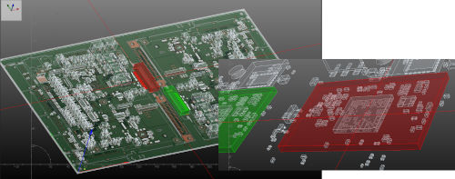 Furthermore, with the 3D visualization of the printed circuit board image and components, users can visualize the assembly almost like a physical model (Figure 1) to see how all the parts should be installed and clearly understand the coordinate and angle data of the components.
Figure 1. 3D visualization brings the boards to life to help quickly create high-quality programs.
Data Editing and Conversion:
Thanks to YsUP applications, production teams can accelerate program creation and improve production quality by generating the necessary component data and verifying correct part assembly before committing to building any board. Real-time drawing allows the user to generate component data while constantly comparing it to graphical images (Figure 2), greatly simplifying the task and helping to avoid errors.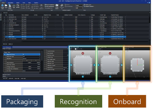
Figure 2. Real-time drawing increases the quality of data creation.
Working in a phase prior to traditional virtual tape analysis, the benchtop proof assembly uses Gerber and CAM data to verify that parts will be correctly positioned relative to their corresponding drawings (Figure 3). Detecting errors at this stage allows for necessary corrections to be made before boards are produced, resulting in higher quality and production efficiency.
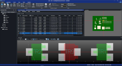 Figure 3. Early verification of component placement, from the desktop computer, improves quality and efficiency.
Automatic conversion tools allow users to start producing boards quickly. Standard CAM data in formats such as ODB++, GenCAD, or FABmaster provides essential information like assembly coordinates, component information, and a board image. The assembly program is then easily created with the click of a button using the standard CAM converter. The CAM converter also handles details such as board panelization and can generate a parts layout image. Finally, the program is automatically optimized for the line setup, and parts and nozzles can be visually checked for interference. Templates assist with feeder configuration.
How to Compensate for Missing Data:
In the past, programming has been hampered by a lack of suitable data about the board to be manufactured. This can be as simple as CAM data and the bill of materials not being available in a format compatible with the CAM converter. Files may express data such as mounting angles or part coordinates in an incompatible way. YsUP now provides standard tools that can convert text data into a format suitable for generating the program.
Gerber Image Tool:
Checking details such as mounting coordinates, polarity, and component angles beforehand can help users ensure their programs directly produce high-quality boards. With YsUP's Gerber Image tool, users can quickly generate high-quality PCB images from the board's Gerber data. When both the board image and Gerber data are available, the tool allows for easy comparison to highlight any discrepancies that could lead to component placement problems in production (Figure 4).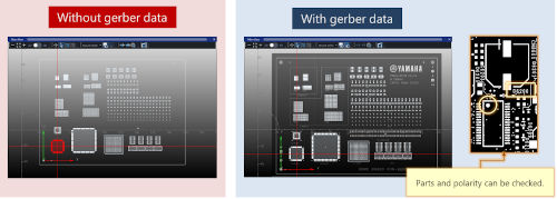
Figure 4. The Gerber Image tool helps correct placement problems in advance from the computer.
In addition, the acquired Gerber data can also be used to generate AOI data, allowing users to start generating inspection programs without having to wait for the physical plates to become available.
Scanner Tool:
On the other hand, there are cases where the necessary Gerber data for creating the board image is not provided. YsUP helps users create a high-quality board image by scanning the raw board and scaling the image correctly using a glass caliper. The board image can then be combined with the converted assembly program using a visual editor.
In extreme cases, there may be no data written on the original printed circuit board. To overcome this, the YsUP scanner tool allows users to scan the actual printed circuit board and automatically create all the necessary data. In other cases, only a paper parts list may be supplied. In this case, the YsUP visual editor can help create the program by dragging and dropping the parts onto the board image. After the user manually places the parts in the correct locations, the tool takes care of aligning each part correctly. This is done by leveraging the tool's machine learning feature.
Automatic Learning and Polarity Checking
: Machine learning compares the board image to the appropriate CAD coordinates and component library definitions to ensure all components are correctly aligned with their associated plan patterns, including pin-1 and polarity markings.
Machine learning automatically corrects up to 1,000 parts per minute for any component misalignment, which can result from incorrect or incomplete data. This can occur, for example, if the CAM data describes the component center and mounting angle data in a way the assembler does not expect. This can prevent the machine from mounting the parts on the board at the correct position and angle. Machine learning corrects the errors and displays the incorrect angle data in the error list. A trace function is provided to help verify the corrections without visually inspecting every part on the board.
Component Library Wizard:
A component library wizard helps create components that are not in the standard component library. The wizard guides the user through providing the necessary parameters for component recognition, such as the number of contacts, wire size, pitch, component center position, and others. It is also possible to add new components to the library using a scanned image of the component, taking advantage of the built-in part scaling tool to verify correct dimensions.
Bill of Materials (BOM) to Avoid Variations:
An additional feature in YsUP to avoid variations helps users manage multiple product variants based on the same underlying PCB. This is common in the automotive industry, where several distinct options are offered using the same board for speed and efficiency. The assembly variation import tool compares multiple bills of materials and generates a variation list that is used to automatically produce an assembly schedule for each bill of materials. The schedule uses a common feeder design to produce all variants, helping to streamline production activities on the shop floor.
Conclusion:
Each successive generation of high-speed SMT placement equipment brings significant innovations to increase assembly speed, enhance flexibility, and minimize human intervention. High-performance software tools that combine powerful management and scheduling applications with automated functions, and the added convenience of 3D graphics, simplify programming and improve program quality, significantly contributing to increased overall productivity.