

The first part, "Smart Battery Backup for Uninterrupted Energy Part 1: Electrical and Mechanical Design" (published in issue 217 of Convertronic), analyzes the electrical and mechanical design considerations of the BBU. The second part delves into the software of the main microcontroller, responsible for ensuring the proper functioning of the processes and, therefore, for guaranteeing the high efficiency and capacity of the BBU. The hardware and software must work seamlessly together to deliver system-level solutions that meet the required specifications.
Introduction
Maintaining good housekeeping practices in the BBU module is essential, as it provides numerous benefits that cannot be ignored. The primary advantage of a neat and organized circuit is the enhanced safety it provides, reducing the risk of electrical fires and other hazards. Furthermore, good housekeeping practices improve circuit performance and longevity by preventing electrical faults that can interfere with its proper operation. It is essential to regularly monitor and organize the circuits to identify and address any problems or malfunctions that may arise. Prioritizing good circuit organization is a simple yet effective way to ensure optimal safety and performance and should never be overlooked. Each BBU module employs a main microcontroller and a battery management system (BMS) microcontroller. In the Analog Devices reference design, the MAX32690, an ultra-low-power Arm® microcontroller, acts as the main microcontroller and is responsible for six important processes (see Figure 1). A MAX32625 acts as the BMS microcontroller for the reference design. The BMS microcontroller is responsible for communicating with the ADBMS6948 and transferring all measured data to the main microcontroller.
The six processes of the main microcontroller are:
► Maintenance and communication via I2C protocol with various peripherals.
► Management of the discharge sequence provided by the backplane voltage data.
► Management of battery charging between constant current and constant voltage modes.
► Transition between the charge and discharge states of the BBU module.
► Fault handling and response.
► Response to Modbus commands as a Modbus follower.
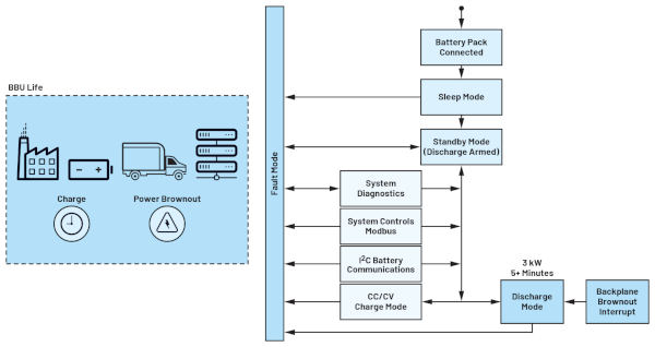
Figure 1. Main controller maintenance operation cycle.1
Main Microcontroller Process:
Maintenance and communication via I2C with various peripherals.
With numerous auxiliary devices connected to the module's circuitry, the main microcontroller functions as a primary I2C interface. The main microcontroller collects and stores data from the auxiliary devices while acting as the primary I2C interface. To perform various tasks, the main microcontroller also controls several auxiliary I2C devices. These auxiliary I2C devices include:
► A BMS microcontroller using the MAX32625.
► An LTC2971, a two-channel power management system.
► A MAX31760, a precision fan speed controller.
► A 24AA512T/EEPROM, which serves as data storage for retrieving and saving important data.
► An LTC2991 temperature sensor.
BMS Microcontroller (MAX32625)
The main microcontroller routinely communicates with the BMS microcontroller (MAX32625) to receive updates on individual cell voltages in the battery pack, state of charge (SOC), state of health (SOH), cell temperature, and any faults that may have occurred in the battery pack. Updates are performed every four minutes, as cell voltages, SOC, SOH, and temperature are not expected to change rapidly. In the event of a fault, a shared pin between the two microcontrollers will be pulled high, triggering an interrupt on the main microcontroller to immediately read the BMS microcontroller and obtain information about the fault. A dedicated I2C port has been provided on the main microcontroller for exclusive communication with the BMS microcontroller to facilitate rapid communication between the two microcontrollers.
The main microcontroller routinely communicates with the LTC2971 via the Power Management Bus Protocol (PMBUS), checking voltage, current, and temperature measurements, as well as warnings and faults. The LTC2971 acts as a fast feedback function by measuring the backplane's output voltage parameters, allowing the main microcontroller to adjust its routine. Additionally, the device ensures that the output voltage remains within regulation during discharge operation by adjusting the power converter's feedback voltage, enabling it to reduce the output voltage by 1%.
(Power Management IC)
MAX31760 (Fan Controller)
The MAX31760 is responsible for regulating the speed of the BBU module's fans. The pulse-width modulation duty cycle is configured by the microcontroller to regulate the fan speed via I2C. The main microcontroller calculates and adjusts the required fan speed based on the temperature and load current of the motherboard or battery.
24AA512TT (EEPROM/Data Storage)
The integrated EEPROM functions as an external storage device for the entire BBU module. The main microcontroller regularly saves vital information, such as battery voltage levels, SOC, SOH, cell type and model year, and board temperatures, to the EEPROM via I2C writes to its flash pages. This data is updated hourly and is accessible to users during maintenance and troubleshooting.
LTC2991 (On-Board Digital Temperature Control)
The LTC2991 is an octal voltage, current, and temperature sensor. This device is used to monitor the battery module's temperature using several digital sensors strategically placed inside the module. Based on its temperature readings, the main microcontroller can adjust the fan speed to ensure that the operating temperature of the power board and battery stack is maintained and never exceeds 40°C.
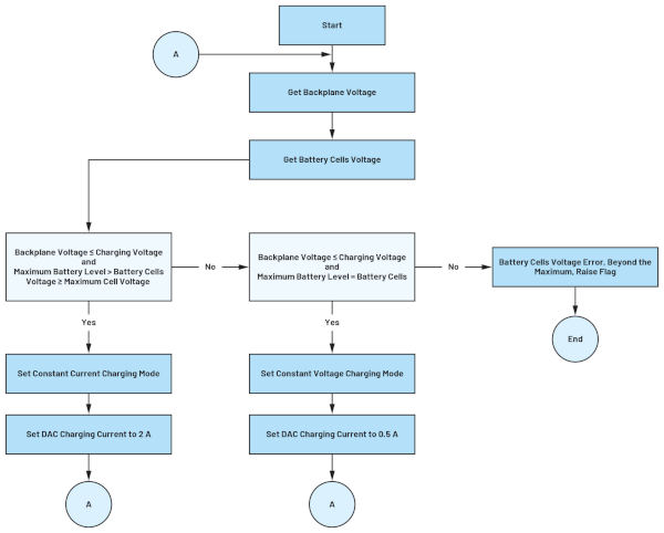
Figure 2. Constant Current and Voltage Charging Algorithm
Battery charging manipulation between constant current mode and constant voltage mode
The main microcontroller is also responsible for managing the battery charging mode. Initially, when the battery cells have an extremely low voltage capacity, the microcontroller allows a maximum current of 5 A to charge them. Once the cells reach a stable state, the microcontroller adjusts the charging current to 2 A until the voltage per cell reaches 4 V. By constantly monitoring the battery cell voltages using data from the BMS microcontroller and employing an analog-to-digital converter to measure the overall battery plane voltage, the main microcontroller determines that once all cells have reached 4 V, it will switch the charging mode to constant voltage mode. This is achieved by limiting the charging current to only 0.5 A. The main microcontroller continues to monitor the overall battery plane voltage level while receiving data from the BMS microcontroller to determine when all batteries are fully charged. This is illustrated in Figure 2.
Power Converter Charge/Discharge State Transition:
It is vital to understand how the BBU transitions from standby to battery power during a power outage. To prevent any unexpected power loss and data loss, the module's main microcontroller closely monitors the motherboard voltage levels. The LT8228's default charge mode is set around 49V to 53V, but if the microcontroller detects the motherboard voltage dropping below 48.5V for 2 ms, it will immediately switch the LT8228 from charge to discharge mode for four minutes to manage the power interruption. The module will continue discharging until the four minutes have elapsed to ensure uninterrupted power. If the battery cells allow it and the backplane voltage supply has not yet returned, the module will wait one minute to allow the cells to cool before switching to discharge mode. Once power is restored, the unit will reconnect to the main power source and begin recharging the battery. For specific instructions on how to operate and maintain your BBU, please refer to Figure 3 to understand this process.
Fault Handling and Response:
It is essential to have a well-defined plan for managing faults. To avoid stress and frustration, it is crucial to identify potential problems in advance and establish a protocol for resolving them. Clear communication with the devices integrated into the system is also necessary to ensure smooth system operation and that everyone knows what to expect. Remember that errors and faults can occur, but how they are addressed can have a significant impact on the outcome. Therefore, the primary microcontroller is specifically designed to reduce the occurrence of false alarms for faults specified by OCP. The microcontroller's firmware program performs an algorithmic check to detect the faults that trigger malfunctions. After detecting a fault, it performs a verification check and only recognizes a fault if the problems occur consecutively or within a specified number of cycles. This ensures that only genuine faults are identified and resolved, which is an intelligent approach.
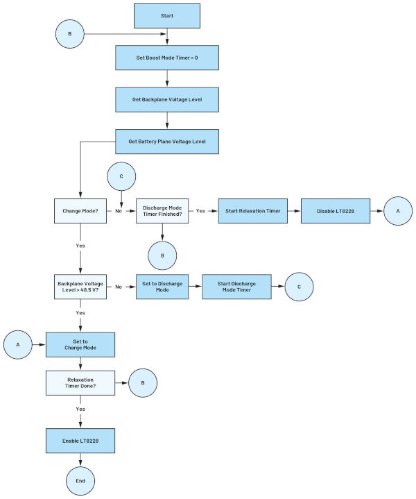
Figure 3. Operation of the charge/discharge module's transition management.
Responding to a Modbus Command as a Modbus Follower:
Modbus function codes are crucial for establishing communication between devices on a Modbus network. They determine the type of request or response sent between devices, such as reading or writing data. Some of the most common Modbus function codes include module metrics, module operating status, module register addresses, and fault status.
The handling of Modbus commands is solely under the control of the main microcontroller. The main microcontroller supports all essential Modbus commands deemed necessary by the OCP specifications. These commands allow modification of module settings or provide vital information about the battery's State of Charge (SOC), its status, cell voltage levels, and charge and discharge currents, among other parameters. Once the main microcontroller verifies the message, it responds according to the command received.
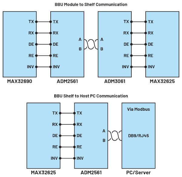
Figure 4. Block diagram of a Module-to-Shelf and Shelf-to-PC communication.
The main microcontroller processes and transmits data from various peripherals to the shelf microcontroller via the UART protocol using ADM2561 and ADM3061, as shown in Figure 4. The advantage of using an isolated transceiver is that data is transmitted over the UART protocol. This isolation is immune to system-level electromagnetic interference and complies with the OCP electromagnetic compatibility (EMC) standard. Shelf-to-PC communication was achieved using the ADM2561, which was connected to the host PC via a DB9 (D-Subminiature) connector and an RJ45 Internet port.
Abstract:
An essential requirement is a controller architecture that is efficient, productive, and remarkably adaptable. It must have well-defined inputs and outputs, as well as the capacity to handle sophisticated algorithm routines. The architecture must be modular to allow for seamless algorithm changes and updates. Furthermore, it must include built-in safety mechanisms to prevent system failures or accidents and easily manage unforeseen events. Overall, a high-quality controller architecture should provide reliable and effective system control while limiting the possibility of errors or malfunctions.
Part 3 of this series will explain the BBU BMS and its associated microcontroller. The article will cover how readable data is processed and used to maintain inter-cell voltage and battery pack temperature. Beyond cell balancing, the implementation of the SOC and SOH algorithms and how this information is used to extend the battery pack's cycle life will be discussed.
References
1 David Sun. "Open Rack/SpecsAndDesigns". Open Compute Project.
About the author:
Christian Cruz is an application development engineer at Analog Devices, Inc. in the Philippines. He holds a degree in electronic engineering from the University of Oriente in Manila, Philippines. He has over 12 years of engineering experience in the fields of analog and digital design, firmware design, and power electronics, including the development of power management integrated circuits, as well as AC-to-DC and DC-to-DC power conversion. He joined ADI in 2020 and is currently supporting power management requirements for cloud-based computing and system communications applications.
About the author:
Marvin Neil Solis Cabueñas graduated with a Bachelor of Science in Electronic Engineering from De La Salle University in Manila, Philippines. Before joining Analog Devices in 2021, Marvin worked as a Systems Engineer for Azeus Systems Philippines, Inc. He then worked as a Network Engineer for Technistock, Philippines, Inc. from 2014 to 2017, and as a Research and Development Engineer for Nokia Technology Center Philippines from 2017 to 2020. He has over nine years of work experience in various fields, including embedded systems programming, digital signal processing, simulation modeling, and others. He currently works as a Senior Firmware Engineer on several projects for ADI's Energy Business Unit. He is currently pursuing a Master of Science in Electrical Engineering at the University of the Philippines.