We monitor aspects of the physical environment around us using an ever-increasing number and variety of sensors. These generate signals that are typically low-amplitude and noisy in nature. They often lack linearity and, in most cases, must be transformed from their real-world analog form into digital values suitable for computer systems. Each signal chain that cleans and transforms these raw measurements, acting as a bridge between the sensor and the computing or processing resource, plays a critical role in the growing demand for data.
Common characteristics of the signal chain
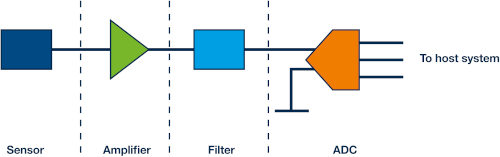
In general terms, a signal chain consists of a series of key elements. Namely: the sensor (or the hardware that captures data), signal amplification and filtering, followed finally by an analog-to-digital converter (ADC) that samples and digitizes the conditioned signal for further processing or storage.
One or more amplification stages may be required, such as a transinductance amplifier (TIA) followed by a voltage gain amplifier. In addition, several filters may be necessary to isolate the signal within a given frequency range, apply anti-overlap to high-frequency signals, and eliminate unwanted signals at specific frequencies (e.g., AC mains interference). Depending on the sensor output, it may be advantageous to amplify the signal before filtering, as any noise will also be amplified. Alternatively, filtering can be applied first.
 A successive approximation register (SAR) or a sigma-delta ADC may be the most suitable solutions for digitizing the filtered and amplified signal. SAR ADCs typically have lower latency than sigma-delta devices, although their maximum sampling rate is usually lower. The strengths of sigma-delta ADCs include their high resolution and energy efficiency, and they often also incorporate additional features (such as filters, multiplexers, or input buffers).
Figure 1: Basic components of the signal chain.
Industrial temperature monitoring case
Temperature is said to be the most commonly monitored element in the physical world. A thermocouple can detect extremely high temperatures in industrial environments, but the output voltage is small (typically only a few mV). The components of the signal chain (as shown in Figure 2) must ensure high amplifier gain with low noise and low drift.
A reference temperature must also be monitored to provide cold junction compensation (CUF), enabling the instrument to generate an output voltage that corresponds to the temperature detected at the thermocouple probe. CUF is typically implemented using a resistance temperature detector (RTD) or a silicon-based temperature sensor. An RTD requires an excitation voltage that must be supplied by the signal chain design.
Thermocouples, RTDs, and thermistors all exhibit non-uniform linearity that must be corrected within the signal chain. For thermocouples, the output voltage variation for a given temperature change is determined by the Seebeck coefficient. However, this coefficient is not constant across the thermocouple's operating temperature range, so it is best to select a type that provides the most linear response possible within the intended operating temperature range. Design engineers can consult the IPC categories, which standardize the properties of different thermocouple types. For example, an IPC Type S thermocouple has an approximate useful temperature range of 0°C to 1500°C and exhibits reasonable linearity from approximately 900°C to 1250°C. Reference tables for standard thermocouple types, such as those published by the U.S. National Institute of Standards and Technology (NIST), allow for digital linearity correction and avoid the complexity of correcting linearity within the signal chain itself.
Figure 2: Example of a thermocouple signal chain.
Each physical electrical connection of the thermocouple inevitably creates an additional thermal junction, so it is essential to ensure that all connections—except for the temperature sensing probe and the cold junction—are at the same temperature.
Case of medical or physical condition monitoring
The growing desire for self-quantification and faster, more cost-effective healthcare models is driving demand for simpler detection systems for bioindicators (such as body temperature, blood oxygen, and heart rate), whether through clinical-grade instruments or consumer-oriented devices (such as fitness trackers). Compared to thermistors and RTD temperature sensors, which require considerable signal processing, silicon-based temperature sensors are more linear, stable, and user-friendly. Although their temperature range is narrower (55°C to 150°C), it is more than sufficient for monitoring body temperature using medical devices.
The MAX30208 is a clinical-grade digital temperature sensor optimized for simple, non-invasive body temperature measurement. The temperature level is measured on the top of the sensor, which is easiest to place on the skin and least affected by self-heating issues (due to the power supply current entering through the IC pins). The mounting design is optimized for flexible printed circuit boards that can be positioned at a distance from the host processor, and the I²C interfaceallowsmultiple sensors to be daisy-chained to obtain data from various points on the body for optimal accuracy. The MAX30208 measures body temperature with an accuracy of ±0.1 °C and contains integrated signal chaining circuitry and a 32-bit FIFO for easy interaction with the host processor.
Regarding cardiac activity monitoring, clinical-grade monitors have traditionally relied on electrocardiographic (ECG) signals from various sensors placed on the body. Recently, optical photoplethysmographic (PPG) detection has been developed, offering acceptable accuracy from a small, non-invasive, wearable device such as a fitness tracker or fingertip pulse oximeter. PPG detection works by transmitting light through body tissues and measuring the reflected or transmitted signals. Small changes in blood volume can be quantified, allowing for the calculation of indicators (including blood oxygen saturation, heart rate, and respiration). It also allows for conclusions to be drawn about tissue health and organ function.
The voltage signal from the optical sensors of a PPG instrument contains a DC component associated with blood volume and the optical properties of bones and tissues, with an AC component produced by changes in blood volume corresponding to the heartbeat. Smaller signals generated by activity (such as respiration) are also present.
The signal chain design of a wearable heart rate monitor begins with the transmitter, which can be a green LED or a combination of red and infrared LEDs. The wavelength and intensity of the source determine the penetration depth and strength of the received signal and can be adjusted for optimal accuracy. Furthermore, the LED drivers introduce noise into the transmitted signal, and power consumption must also be considered.
The receiving signal chain must sample the photodetector output and handle ambient light cancellation, filtering, and analog-to-digital conversion. The photodetector output is a current signal with an amplitude ranging from less than 1 nA to tens of µAs. A TIA (Transformer Analog Interface) is required to convert the current signal to a voltage, and the signal chain design must consider factors such as signal dynamic range, signal-to-noise ratio (SNR), board utilization, and the power consumption associated with components like anti-overlap filters and the TIA. Fortunately, the large and growing market for consumer-oriented heart rate monitors allows engineers to choose an integrated analog front end (AFE), such as the Texas Instruments AFE4405 or the Maxim MAX30112 , each of which incorporates the LED driver and a complete photodetector signal chain within their respective single-chip solutions. These devices provide a suitable mechanism to overcome challenges such as photodiode current manipulation, filtering, storage, amplification, and conversion using a sigma-delta ADC.
Case study in image acquisition and processing
Parameters such as human heart rate and industrial process temperatures are relatively simple and stable, placing moderate demands on the signal chain in terms of speed and sampling rate. The MAX30112 supports a sampling rate of up to 3.2 kSPS to meet the needs of pulse oximetry or heart rate monitoring applications. Signal speeds and sampling rates in applications such as image detection or industrial machine vision are much higher and require special attention.
Simple imaging systems, such as near-infrared spectroscopy equipment for materials inspection or analysis, may employ a linear photodiode that requires cooling to minimize the effects of thermal noise and signal conditioning. ADA4807 has a -3 dB bandwidth of 180 MHz and is particularly well-suited for use with theADAQ7980 single-chip data acquisition system, which contains a low-noise 1 MSPS SAR ADC. This system adapts power to the sampling rate, maximizing efficiency. Integrating a low-input, wideband ADC driver and a rail-to-rail output to minimize distortion eliminates unwanted complications for design engineers, such as circuit design and component selection. The internal power architecture and the provision of a precision external voltage reference also help preserve signal integrity by reducing system noise.
Machine vision with high-speed cameras and video surveillance applications place even greater demands on signal acquisition. A high-speed frame capture device establishes the connection with the camera and interfaces with the host PC (typically via PCI or PCI Express) using a communication protocol such as Camera Link, which defines video processing speeds from 255 Mbps to 680 Mbps. The frame capture device also typically implements important video preprocessing functions, such as gain control, dead pixel compensation, and dynamic range expansion. This often needs to be done at real-time frame rate. Designing a frame capture device is a considerable engineering challenge, often met with FPGAs that provide the required signal processing performance and can house machine vision algorithms on the same device.
Conclusion
Capturing sensor signals to obtain informative data for any application—consumer, industrial, or medical—requires a thorough understanding of each component in the signal chain. This encompasses everything from the sensor to the ADC, and in each case, the correct elements must be selected and properly integrated. In many cases, a single-chip front end is already available, which can effectively simplify the design and reduce time to market.