However, when designers create image payloads with sufficient resolution to meet the needs of satellite operators, they encounter the perennial problem of downlink bandwidth limitations. For low Earth orbit (LEO) imaging satellites that generate tens of gigabits per second of data and complete Earth orbits approximately 16 times a day, it is impractical to send a constant stream of data to Earth over a space relay network. Historically, image data was compressed and stored onboard the satellite; however, more efficient use of the data relay network that provides the connection to the ground station can be achieved by performing more data processing onboard the satellites so that the information can be transmitted to Earth, rather than remaining as raw data. This has led to an explosion in the demand for components capable of achieving the necessary high data processing rates while simultaneously meeting stringent radiation tolerance requirements.
Advances in artificial intelligence and machine learning (AI/ML) have created exciting opportunities to optimize downlink bandwidth usage, for example, by eliminating images that contain no relevant data (e.g., on a satellite monitoring land use, images where the ground is obscured by thick cloud cover would be useless; or on a satellite tracking maritime traffic, ocean images where no ships are visible). Furthermore, AI/ML enables the automation of onboard decision-making, reducing or eliminating the human analysis that can add days or weeks of latency to image data deployment.
As space mission requirements evolve, there is a clear and persistent need for the latest technology in space assets; however, any product deployed in space must meet the fundamental requirements for sustainable and reliable operation.
The need for faster revisit rates for Earth observation imaging drives the requirements for field satellite constellations, which in turn drives the need to reduce satellite acquisition costs.
Preparing a commercial component for use in space applications requires three key steps: radiation assessment, envelope, and qualification.
Radiation Assessment:
The effects of radiation in space are widespread and orbit-dependent. The effects of radiation on any component intended for space must be assessed, as radiation can cause physical damage to the component and the consequent loss of functionality of critical satellite equipment. Table 1 summarizes the effects of radiation in various Earth orbits. Table 1: Effects of radiation in Earth orbit.
The effects of radiation in space are divided into two main categories: total ionizing dose effects and single event effects.
Total ionizing dose (TID) refers to the long-term accumulation of radiation. In most microelectronic devices, TID leads to performance degradation and increased leakage current. TID can even cause a complete loss of functionality. The effects of TID can vary with small variations in the wafer fabrication process, so microcircuits intended for space applications are often offered with batch-by-batch TID testing. The successful deployment of any microcircuit in space depends on a thorough understanding of the TID effects for the devices to be used.
Single-event effects (SEE) refer to the result of a microcircuit's interaction with a single subatomic particle. In space applications, this is typically a proton or a heavy ion; in aviation applications, it is typically a neutron. Single-event electrical errors (SEEs) can be divided into several subcategories: single-event latch-ups, single-event upsets, single-event transients, and single-event functional interrupts.
A single-event latch-up is a phenomenon in which a parasitic PNPN structure becomes forward-biased due to ionization caused by a heavy ion, driving current levels that can cause irreversible damage to the integrated circuit.
Single-event upsets occur in flip-flops and integrated memory elements due to the current surge resulting from the ionization and subsequent recombination of silicon atoms when a heavy ion passes through a microcircuit. Designers have several mitigation methods available, such as triple modular redundancy (TMR) for flip-flops and error-detection and correction encoding and decoding (EDAC) for memories.
While single-bit mismatches in flip-flops or embedded memory cells may have limited consequences, they can be catastrophic if they occur in the configuration memory of an SRAM-based FPGA. In this case, a single heavy ion can cause unintended changes in the FPGA's functionality (Fig. 1). Mitigating these configuration alterations requires significant system overhead in the form of configuration cleanup and repair.
 Fig. 1: Effect of heavy ions on the functionality of FPGAs.
Transient changes in signals caused by the effects of single-event radiation in combinational logic are called single-event transients (SETs) and can be problematic if the transient is present at a register's data input at the exact moment the register is synchronized. In this case, the transient is preserved as a single-bit disturbance. As the clock frequency increases, the probability of capturing a transient also increases.
Any single radiation event that causes a change in the function of an integrated circuit is called a single-event functional interrupt. As integrated circuits become more sophisticated, the number of ways in which single-event functional interrupts can occur increases dramatically.
The successful deployment of any microcircuit in space depends on a thorough understanding of the radiation effects on the devices being flown. Therefore, it is important for organizations developing spaceflight hardware to have test data available for the exact batch of wafers supplied with flight components. Evaluating the effects of radiation requires destructive testing. Flight units cannot be subjected to radiation effects testing, as this would severely impact the expected lifespan of the components. Testing for the effects of radiation is performed by sampling each batch of wafers. Single-event effects testing is conducted early in the product's life, as the effects of a single event depend on the IC design and tend not to be as variable with the wafer manufacturing process. Special care must be taken with commercial components, as any shipment of commercial components may originate from different wafer batches, even different pellet revisions, or even different foundries, which can drastically increase the variability of radiation effects on the components. Without strict traceability, it is impossible to be certain that the components subjected to radiation testing are representative of the components in use. In contrast, microcircuits offered for spaceflights typically have full batch traceability, and the device manufacturer can provide TID test data for the specific wafer batch from which the flight components originate.
Packages:
Most microcircuits used in high-reliability satellites are housed in hermetically sealed ceramic packages. There are three main reasons for using ceramic packages. The first relates to the inspectability of ceramic packages. Military standards governing the manufacture and testing of components for use in space systems (e.g., Mil Prf 38534, Mil Prf 38535, and Mil Std 883 Class B) require third-party inspection of the integrated circuit within the package before sealing to verify the quality of the assembly. Inspection is easily performed on ceramic packages before the lid is sealed.
Another advantage of ceramic packages is that, at extreme temperatures or in a vacuum, the ceramic material does not emit vapors, a phenomenon known as out-gassing. In contrast, plastic packages can emit vapors, which can cause optical components to fog up in space.
The final advantage of hermetically sealed ceramic packages is their ability to protect the microelectronic components inside from harmful moisture or board cleaning fluids during space hardware assembly and integration.
For these reasons, hermetically sealed ceramic packages are essential for the most demanding, high-level missions, such as national security space missions and crewed spaceflight missions.
Ceramic packages face some growing and significant challenges as performance requirements increase. The larger number of I/O pins required by modern integrated circuits necessitates that the pins for signals, power supplies, and ground be mounted in a 2D array on the underside of the package, rather than a linear arrangement of pins around the outside of the package, as implemented in some traditional packages such as ceramic quad planar packages (CQFPs). The mismatch in the coefficient of thermal expansion between the package and the board causes mechanical stress that can shear off ordinary solder balls as the printed circuit board traverses the extended temperature range. To solve this problem, solder columns are used instead of solder balls. Solder columns are mechanically flexible and absorb the mechanical stress associated with the different rates of thermal expansion of the board and the ceramic package.
An additional challenge for ceramic packages relates to their electrical properties. The latest on-board signal processing systems are being designed with serial data interconnectivity between integrated circuits and between circuit boards, with data rates reaching 10 to 12 Gb/s. Ceramic packages can keep up with these demands. However, the next generation of systems will exceed these data rates, posing a challenge to current ceramic package technology. Ceramic package suppliers are responding to this challenge with new technologies that are currently being evaluated.
Due to the challenges posed by using ceramic packages, some space programs are planning to use integrated circuits with plastic packages. Plastic packages have the advantage of having fewer electrical parasitic effects than ceramic packages, allowing for higher performance in high-speed I/O. Furthermore, the coefficient of thermal expansion of plastic packages is much closer to that of the printed circuit board material, which drastically reduces mechanical stress on the solder balls, eliminating the need for solder columns and thus promoting greater efficiency.
Qualification:
The tests performed during IC qualification for space use depend on whether the IC is integrated into a ceramic or plastic package.
For ICs with ceramic packages, qualification is performed according to an established standard, such as Mil Prf 38535 or an equivalent ESA specification. Most US-based suppliers comply with Mil Prf 38535. The main qualification steps are listed in Table 1. There are two qualification levels specified in Mil Prf 38535, known as QML Class Q and QML Class V. QML Class Q is intended for high-reliability defense applications, and QML Class V is intended for the most reliable space applications. The main difference between QML classes Q and V is that class V has the strictest qualification requirements, such as a 4,000-hour high-temperature operational life test for the qualification sample, compared to 1,000 hours for class Q.
Examples of integrated circuits in ceramic packages are Microchip's radiation-tolerant RTG4 FPGAs, which achieved their QML class Q and class V qualifications in 2018 (Fig. 2).
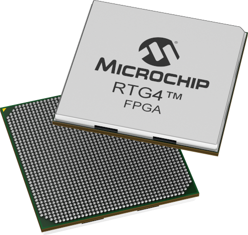 Fig. 2: Microchip RTG4 radiation-tolerant FPGA.
For integrated circuits in plastic packages, there is no qualification standard agreed upon by the entire space industry. When plastic packages are offered for space applications, qualification activities are based on JEDEC standards. Major suppliers and consumers of integrated circuits in the space industry are collaborating on the definition of a Quality Management Line (QML) standard for the qualification and control of plastic-packaged integrated circuits for space use, within the framework of a JEDEC committee. Once a QML standard for the qualification and screening of plastic-packaged microcircuits for space use has been agreed upon, many IC suppliers currently supporting space products are likely to offer microcircuits qualified and screened according to that standard.
New Alternatives:
Satellite service providers are seeking to open new markets or create new capabilities, such as global communication networks and high-revisit-rate surface imaging. These operations require satellite constellations. To keep the cost of deploying large numbers of satellites manageable, satellite designers often use components not specifically designed for radiation environments or space deployment. The risk is that off-the-shelf (COTS) components often lack space heritage, space qualification, or even wafer batch traceability or homogeneity, so radiation data collected from a sample is not necessarily representative of parts intended for spaceflight.
In response, some microcircuit manufacturers are offering radiation-tolerant components without the full suite of space-level QML testing. For example, Microchip's RTG4 radiation-tolerant FPGA family is currently available in a plastic ball-array package, which is being qualified according to JEDEC standards. Developing a "Sub-QML" product like this offers designers of large-scale satellite constellations an alternative approach that eliminates QML screening to save costs. The use of radiation-tolerant microcircuits provides a high level of radiation assurance and legacy protection for space missions and avoids the lack of traceability associated with COTS components.
The evolving needs of space designers are driving the demand for high-density, high-performance integrated circuits. The harsh environment of space requires a high level of radiation tolerance and robust reliability in components intended for space applications. Whether plastic or ceramic packages are used, a well-defined set of qualification and selection requirements is essential to ensure the success of future space missions. Established manufacturers of space-grade microcircuits are rising to the challenge and offering an expanded product range that includes traditional QML-qualified components and Sub-QML devices that combine the advantages of radiation tolerance and traceability with lower-cost packaging and screening.
Author: Ken O'Neill, Associate Director, Space and Aviation Marketing, FPGA Business Unit, Microchip Technology