
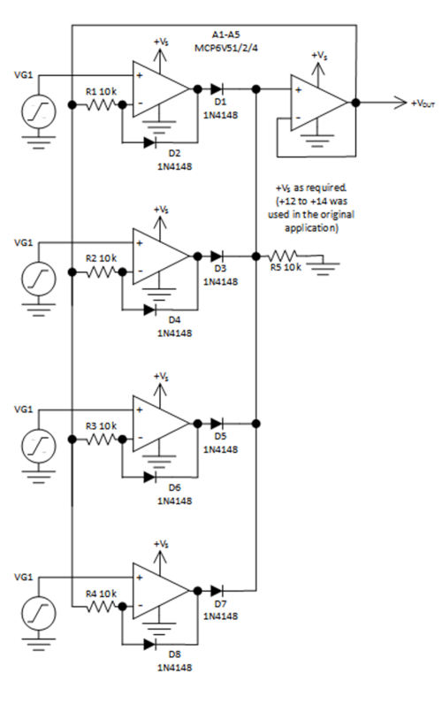
Figure 1 The input priority amplifier provides an output from the most positive of four inputs. This circuit responds to positive inputs, but by reversing the diodes and reconfiguring the power supplies, it can respond to negative inputs.
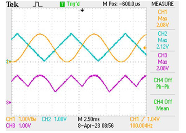
Figure 2. Simulation graph of the output of the 4-channel priority amplifier.
In the circuit, the amplifier with the most positive output controls the negative feedback path through the forward-biased diode at the amplifier's output. This forms a simple unity-gain path through R1 or R2, R3 or R4, depending on which channel is the most positive, to the amplifier's inverting input. The diode between the inverting input and the output is reverse-biased at the amplifier with the largest input, causing the circuit to function as a unity-gain amplifier from its input to the overall output. The outputs of the amplifiers with weaker inputs are forced to become negative from the output value until their feedback diode, D2 (or diode for any corresponding amplifier), is forward-biased, thus keeping the amplifiers in a local closed-loop condition. The 10kΩ resistors, such as R1, allow the weaker amplifiers to function as unity-gain buffers by forming a local feedback network. Figure 2 shows simulation results using all four channels.
Figure 3 depicts actual operating traces on two inputs, Channel 1 and Channel 2, with the output shown as Channel 3.
Dissimilar input signals are applied to dramatize the effect when two different waveforms compete for the highest amplitude at various intervals. Figure 3 shows actual oscilloscope traces of a two-channel version of the amplifier with the output on Channel 3 (note that the zero for Channel 3 is lower on the oscilloscope screen than the zero for Channels 1 and 2).
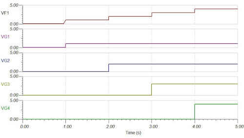
Figure 3. Oscilloscope graph of a two-channel version of the priority amplifier. Channels 1 and 2 are input signals, and Channel 3 is the output. (Note that the zero for Channel 3 is lower on the oscilloscope screen than the zero for Channels 1 and 2.)
Although this circuit is configured to operate with positive voltages, adapting it to negative voltages simply involves reversing the diode connections and setting the power supply voltages accordingly.
While the circuit shown uses a Microchip MCP6V51/2/4 operational amplifier, a wide selection of Microchip operational amplifiers could be suitable. Considerations in the selection include:
1. Multiple, such as quad, operational amplifiers (and multiples of multiples based on the final number of lines).
2. Often, most applications will require an operational amplifier with a common-mode range that includes the operational amplifier's negative supply rail, which is typically ground. In some cases, a common-mode amplifier with a rail-to-rail range may be necessary.
3. It should be obvious that the sensor or input signal levels, as well as the output signal requirements, determine the required voltage rating of the operational amplifiers.
4. Unity-gain stability is essential for this circuit. Using it with the output across capacitive loads may require additional compensation to maintain stability.
Author bio:
Jerry Steele has over 30 years of experience in analog and power electronics, having worked at Apex, National Semiconductor, TI, and ON Semiconductor. His roles have ranged from Applications Engineer to Strategic Development Engineer, and he currently serves as a Validation Engineer for Microchip.