Docking stations and high-performance computing equipment, where compact enclosures must sustain high power levels, are a prime example.
Traditional two-level DC-DC converters, while tried and tested and widely adopted, are reaching their performance limits in these scenarios. Switching losses, component stress, and thermal limitations have become limiting factors. The three-level DC-DC converter architecture offers a solution, providing significant improvements in efficiency, thermal headroom, and power density.
How a Three-Level DC-DC Converter Works:
A three-level DC-DC converter introduces an intermediate switching node between the input voltage and ground. Instead of oscillating a switching node across the entire input voltage, the topology divides the voltage in half during each switching cycle using a pair of capacitors (often called a flying capacitor arrangement).
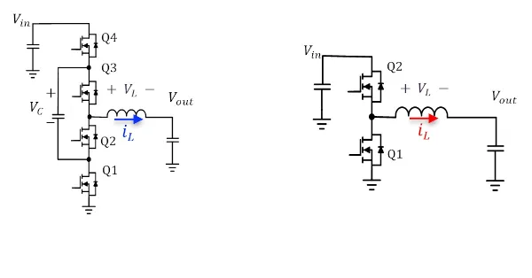
Figure 1: 3-level vs. 2-level DC-DC converter topologies
The main advantages are:
1. Reduced switching voltage swing: each MOSFET only sees half the input voltage, reducing switching losses and allowing the use of lower-voltage MOSFETs with lower RDS(on).
2. Lower component voltage: capacitors, MOSFETs, and magnetic components can be selected from higher-performance, lower-voltage product families.
3. Reduced switching losses: the energy lost per transition, proportional to V², is significantly reduced.
Efficiency Advantages:
In high-voltage step-down scenarios, 3-level converters typically achieve efficiencies exceeding 98%. For example, in a 48V to 20V USB-PD EPR stage, switching losses can be reduced by more than 40% compared to a two-level design.
Thermal benefits:
- Lower losses mean less heat per watt supplied.
- Designers can reduce heat dissipation or drive higher power density without exceeding thermal limits.
Inductor and FET (3N) temperatures


Figure 2: Comparison of the thermal performance of 3- and 2-level DC-DC converters
Example of Efficiency and Thermal Calculations
To illustrate the thermal and efficiency advantages of the 3-level DC-DC topology, consider a 48 V to 20 V, 240 W EPR USB-PD stage operating at 300 kHz. The following calculations use realistic but illustrative MOSFET parameters for two- and three-level buck converters.
Assumptions:
- Vin = 48 V, Vout = 20 V, Iout = 12 A, fs = 300 kHz
- Two levels tr/tf = 15 ns, Coss_total = 400 pF, Qg = 18 nC, Rds(on) = 10 mΩ (per FET) two in series per path)
- Fixed losses (controller etc.) = 0.25 W

The switching losses (P_sw + P_coss + P_gate) are reduced from 3.04 W in the two-level case to 1.54 W in the three-level case. The inductor loss is reduced from 2.2 W to 0.98 W. End-to-end efficiency improves from 96.9% to 98.1% for the same 240 W output power.
From a thermal perspective, the reduction in MOSFET losses translates to a much smaller junction temperature rise. In this example, the hottest MOSFET in a two-level design might experience a rise of +76 °C above ambient temperature, whereas in the three-level design, the individual device dissipation is reduced to ~0.85 W, resulting in a rise of only +42 °C under similar cooling conditions.
Real-world application examples:
The advantages of three-level converters are most apparent in compact, high-power applications where every watt and every cubic centimeter counts. In USB-PD Extended Power Range (EPR) adapters delivering between 140W and 240W, reduced ripple current and lower device stress enable thinner inductor designs, resulting in smaller, lighter chargers that run cooler in the user's hand. Docking stations and monitors with integrated USB-C power delivery also benefit, as the reduced thermal footprint allows designers to integrate multiple high-speed data ports without bulky heatsinks. In high-performance computing environments, such as servers, AI accelerators, and peripheral devices, the three-level architecture achieves efficiencies exceeding 98%, minimizing cooling overhead and maintaining reliability under continuous load. Even industrial and medical instruments with long duty cycles benefit from smaller magnetic components and increased efficiency, extending system life and reducing energy costs. These examples highlight how three-level topologies move beyond theory to deliver tangible advantages in diverse markets.
Conclusion:
The three-level DC-DC converter is not just an incremental improvement, but a significant architectural step toward meeting the power density, efficiency, and temperature demands of next-generation electronics. By halving voltage and switching losses, this topology enables efficiency exceeding 98%, reduced component temperatures, and increased reliability.
For engineers designing in the era of USB-PD EPR and beyond, adopting 3-level architectures may be the key to taking the next leap in power delivery performance.
Author: By Alex Zhou, Director of Product Marketing at Renesas