 The decision is often based solely on the cost of the hardware, leaving aside many of the remaining elements.
A standard power module is a component-like device, mass-produced, 100% tested, and guaranteed to meet the datasheet specifications. A discrete power circuit consists of many components mounted on a printed circuit board along with the main system electronics. No further testing is performed beyond the board once it is assembled and finished.
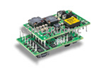
A recent addition to the range of power modules available on the market is the PIM (Power Interface Module). Figure 1 shows an example of a PIM.
A PIM typically incorporates input filtering and transient suppression, inrush current protection, hot-swap functionality, undervoltage hold and shutdown, dual power supply, monitoring, alarms, and PMBus or I2C-based power management. The first available PIM was designed for open platforms based on the ATCA (Advanced Telecommunications Computing Architecture) standard to reduce time to market and save valuable board space; however, the concept and functionality of PIM are actually well-suited to most boards in ICT (information and communications technology) equipment. Currently, this functionality is often achieved through discrete solutions, but this may change as proprietary platforms evolve into more flexible, standards-based open platforms.
There is a wide variety of input power interface solutions for motherboards. Some are very simple, containing only a fuse and EMI filtering. Others are more complex, incorporating inrush current protection, hot-swap functionality, undervoltage hold and shutdown, dual power supplies, monitoring, alarms, and power management.
Power interface circuitry implemented with discrete components on the board is typically a proprietary solution adapted to different distributed power architectures of ICT equipment manufacturers. Standardization initiatives, such as ATCA, have been launched, but proprietary solutions are the most common.
Using a PIM instead of a discrete circuit-based solution offers significant advantages, such as reduced design time and cost, lower purchase and acquisition costs, faster time to market, and less board space required for power interface functionality.
Circuit and System Design Costs:
This cost applies only to the discrete power interface circuit; users of standard power modules do not need to design the internal circuitry. The circuit design cost includes the following:
- Circuit design and layout
- Determining component values
- Specifying component part numbers and alternatives
- Building and testing prototypes, including thermal and EMC aspects
- Modifying circuits as needed
- Documentation
Time and cost will vary depending on the availability of a basic design or whether a completely new design is required. Design hours and hardware costs depend on the number of components and the complexity of the discrete power interface circuit. The outcome also depends on the electrical designer's skill. In fact, a skilled power design engineer is needed to design a robust and cost-effective power interface circuit.
However, there will be a power system design cost for both the discrete power interface circuit and the standard PIM solution. The power system design cost consists of the necessary resources and costs for designing:
- DC distribution and decoupling
- Thermal analysis and cooling
- Safety and fuses
- Controls and diagnostics
The design of the feeding system will be much simpler and faster when using the standard PIM option, as it incorporates much more advanced functions and there is more literature available.
Purchase and Acquisition Costs:
These are the resources and direct costs for purchasing the components required for any solution, including supplier selection and approval, price negotiation, quality assurance, inventory control, etc. For the standard PIM option, there is generally only one component available: the power interface module. Furthermore, in this case, the labor hours and direct costs depend on the number of components and the complexity of the power interface's discrete circuitry.
Discrete power components, like any other power component, are not generally part of the system functionality electronics bill of materials of system board manufacturers, and therefore a certain level of knowledge and engineers are needed to evaluate, train, and certify the components and solution in each application.
Time-to-market cost
is an extremely important aspect related to technical risk and the fact that the initial design is not always final. Sometimes engineering changes and redesigns are necessary when the solution doesn't perform as expected. New microprocessors and ASICs are often developed in parallel with the board design, with some uncertainty regarding the final power circuitry requirements and the overall system supply voltage. Since the focus must be on the performance and functionality of the primary application electronics, the final board power design cannot be considered complete until the main system circuitry has been tested and verified. This means there is an apparent risk that the board's power and interface circuitry will need to be redesigned much later in the project, multiplying design costs and time, which in turn leads to unforeseen delays in the launch and delivery of the new system board. Naturally, there is a greater risk of significant delays when using a discrete power interface solution because the design is not as well-defined or tested and relies on various components and suppliers. Using a standard PIM solution can bring the power system online sooner, potentially increasing sales.
 The time-to-market cost is accounted for as lost revenue and profits due to the drop in product sales in the initial stage if the product launch is delayed because of the food solution development plan. This not only represents a loss in the number of products sold, but also means that being one of the first, or even the very first, to reach the market can account for a significant portion of total revenue and profit, as there is less competition and therefore a considerably higher market price. The time-to-market cost can be a substantial amount when compared to other costs to consider. With the current short product lifecycles, this could very well be the deciding factor in achieving profitability.
Printed circuit board cost
The cost of the surface area occupied by the PIM or the discrete power interface circuit on the circuit board consists of:
- Cost of the board material itself
- Value of the board surface to the system designer
The value for the system board designer can vary considerably. In some systems with less dense boards, this cost can be relatively low. For high-density systems with closely packed packages, the system designer may want to minimize the area occupied by power and power interface functions to accommodate other system application circuitry. In this case, the system board designer and the system manufacturer may assign a higher value to this component, which will serve to impose a cost penalty on lower-density power solutions.
 In practice, this has become one of the biggest challenges for ICT system manufacturers and suppliers. Available space is extremely limited everywhere, and its cost is very high. Indoor and outdoor applications demand the smallest possible footprint and the smallest possible equipment dimensions. Another limitation is that modern high-speed electronics require very short distances to minimize distortion caused by terminal inductance and board capacitance. Therefore, a certain amount of functionality must be included on the board itself.
Printed circuit boards are manufactured in specific standardized sizes, and equipment cabinets and shelves are designed for specific board sizes. Therefore, it is not possible to increase the board size in a given system or piece of equipment; the only solution is to minimize the size and number of components on the board. This contributes to greater integration and a smaller device package size, but at the same time, the need for greater functionality implies a higher number of pins on each microprocessor or ASIC package. The result is a very expensive board, not only due to the costly system electronics but also because of the extremely large number of layers required to achieve functionality. It's not uncommon to find up to 30-40 layers in advanced ICT boards.
All this means that board space is very expensive in modern ICT equipment, and anything that is not part of the main system electronics required for the necessary functionality must be limited to an absolute minimum in terms of board space.
Application Examples
The first example is a board with conventional power interface circuitry (see figure 2).
The power interface was designed long ago and has been used on many different boards for many years because it works, and there are no power design engineers trained to introduce improvements. The components are old and expensive, and the circuitry occupies a fairly large area of the board. There is also a growing demand for system availability and the requirement for hot-swapping, so the power interface needs to be redesigned to incorporate alarm and power management. A PIM will solve all these issues at a lower cost and with a significant reduction in board space.
The second example (see figure 3) illustrates the space that can be saved on the board when using the new PIM4006 micro-PIM module in 1/16 brick format (see figure 4), which in addition to conventional input circuitry includes an I2C interface.
This module has been developed to meet the highest demands for system availability and robustness, and also includes a digital communication interface for system architects to monitor the application status via software. The use of state-of-the-art technology to increase the amount of filtering has resulted in significant space savings on the board (on both sides). This space can be used for greater system processing capacity, simplified power management, and faster time to market.
In this case, a PIM can also save valuable board space and cost. This is possible thanks to an optimized design by specialized and experienced power design engineers. The PIM uses components with smaller packages and advanced solutions, but the bill of materials remains reduced. Power management and internal communication enable a reduction in the required retention time, thus minimizing capacity. The result is a PIM that occupies at most only one-third of the surface area that a discrete design would require.
Standardization in distributed power for ICT equipment will continue to meet the demands of telecommunications and data communications operators as a second supply option due to its lower cost.
The new PIMs under development adapt to different distributed power standards and power levels, as well as to proprietary solutions, making them a viable option in most applications.
Author:
Patrick Le Fèvre, Marketing and Communication Director, Ericsson Power Modules